32ビットマイコンが今なら120円。
ということで STM32マイコン STM32G031J6M6 を買ってみた。
これで ストロベリーリナックス I2C低電圧キャラクタ液晶モジュール(16x2行) を動かしてみる。
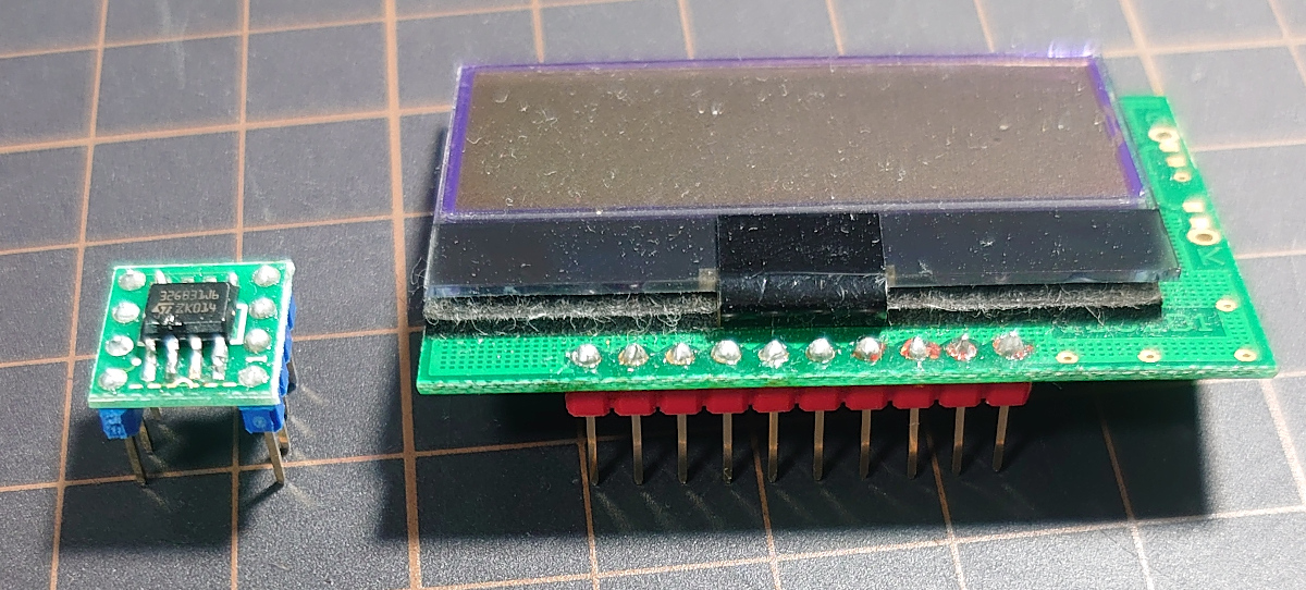
ピンヘッダをつける
細ピンヘッダとDIP変換基板をはんだ付けする。
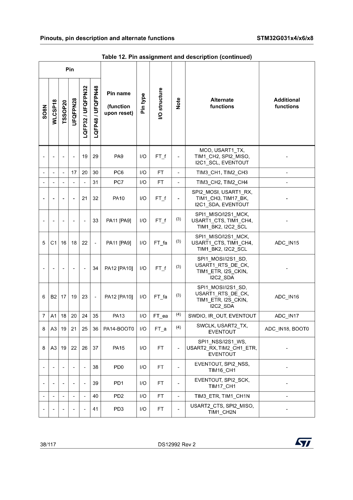
データシートを確認する
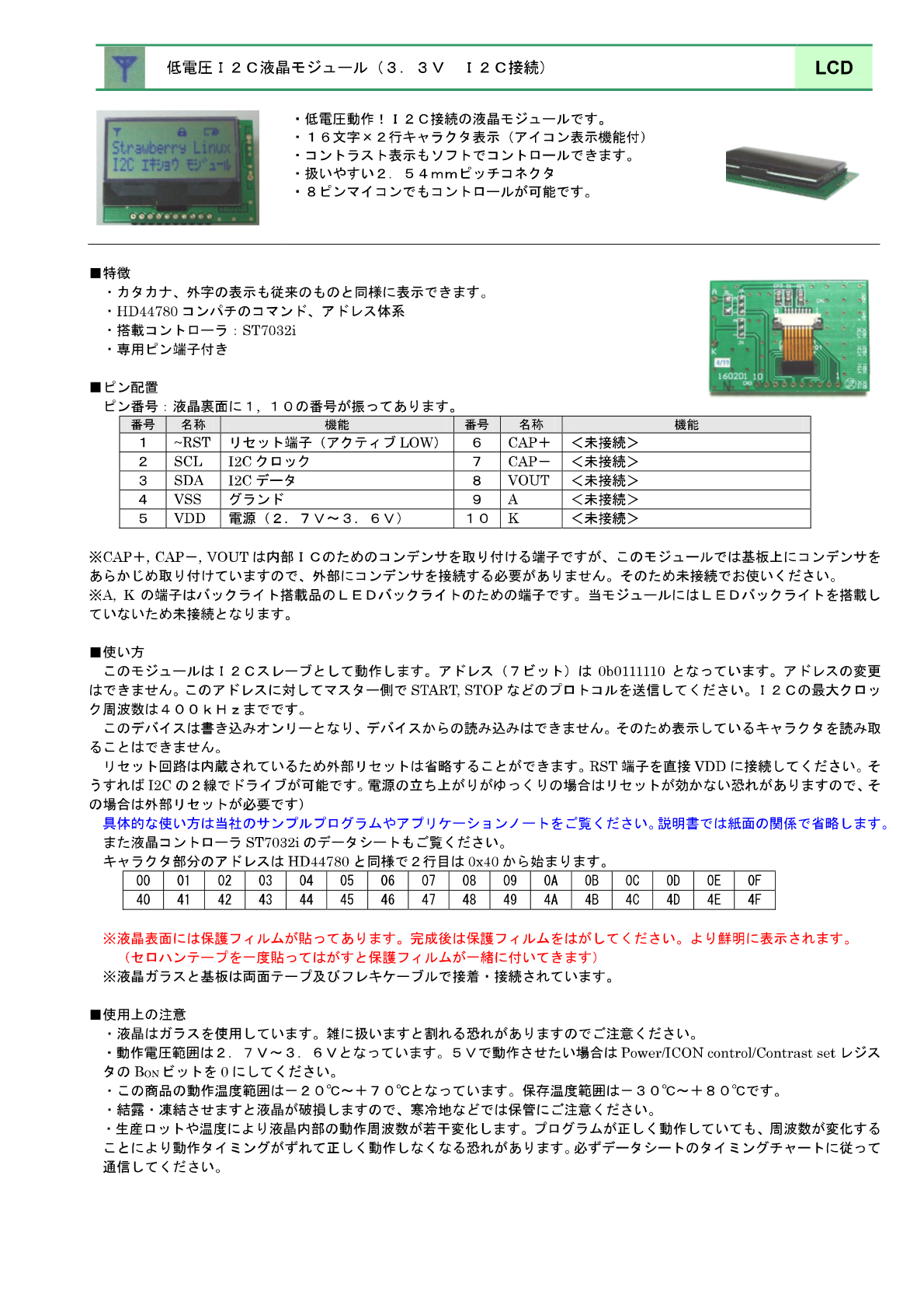
- I2C低電圧キャラクタ液晶モジュールの電源電圧 2.7V ~ 3.6V
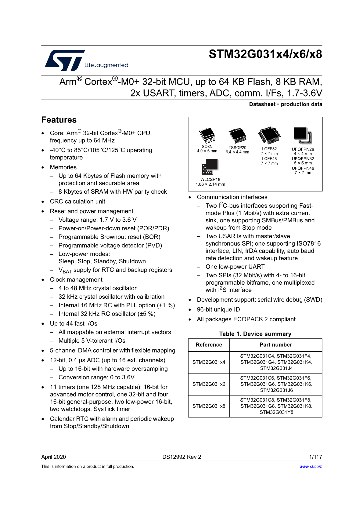
- STM32G031 の電源電圧 1.7V ~ 3.6V
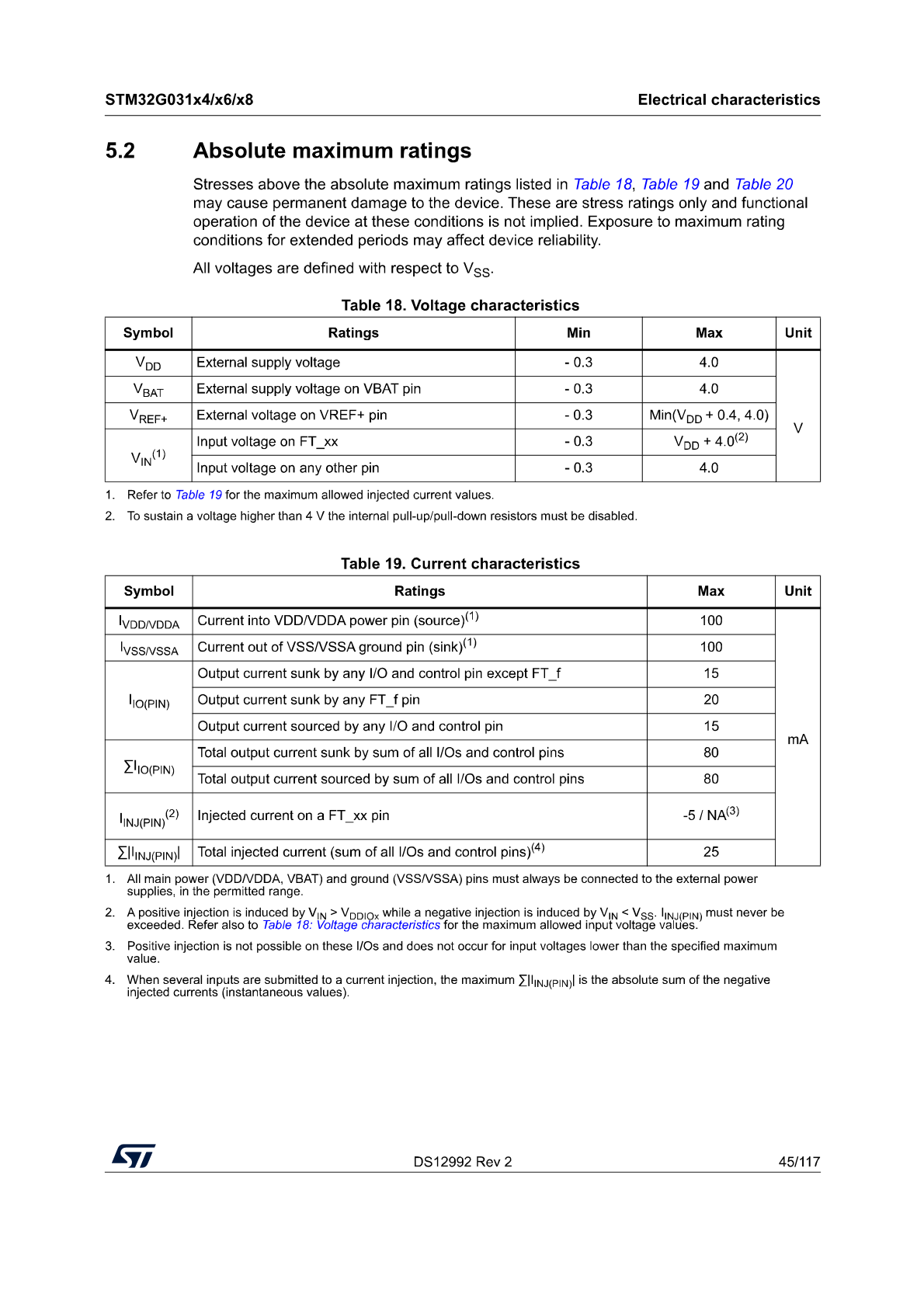
- STM32G031 の絶対最大定格より
FT(5V tolerant I/O)ピンとその他のI/Oピンを含めて各ピン入出力15mAまでに抑えておこう。
今回は電源電圧3.3V(3V3)に決めたので3端子レギュレータで3.3Vを供給する。
STM32とLCDを接続
STM32G031J6M6の
- pin 1 (PB9) — 赤色LED(Vf=2V) — 抵抗R(3k) — VDD(3V3)
- pin 2 (VDD) — VDD(3V3)
- pin 3 (VSS) — GND
- pin 4 (NRST) を I2CLCD のリセットピン(#1)と接続
- pin 5 (I2C2_SCL) を I2CLCD のSCLピン(#2)と接続
- pin 6 (I2C2_SDA) を I2CLCD のSDAピン(#3)と接続
pin 4 (NRST) は GNDとの間にリセット用タクトスイッチを入れて, 抵抗R(3.9k)でプルアップしておく。
pin 5, 6 (SCL, SDA) は抵抗R(3k)でプルアップしておく。
抵抗値に深い意味はない(そこにあったので)。
I2C低電圧キャラクタ液晶モジュール(16x2行)の
- pin 1 (~RST) — STM32G031J6M6 pin#4
- pin 2 (SCL) — STM32G031J6M6 pin#5
- pin 3 (SDA) — STM32G031J6M6 pin#6
- pin 4 (VSS) — GND
- pin 5 (VDD) — VDD(3V3)
接続した後に気になったのでI/Oピンに流れる電流を計算してみる。
LCDに流れる電流は無視できるほど小さいのでLEDのピンに流れる電流を計算する。
直列接続なのでI/Oピンに流れる電流と抵抗器に流れる電流は同じとみなすと単なるLED電流計算になるので
VDD = 3.3V, LEDの順方向電圧Vf = 2.0 V, R = 3kΩ
の場合に
抵抗器に流れる電流を計算すると
気にする必要などなかった。
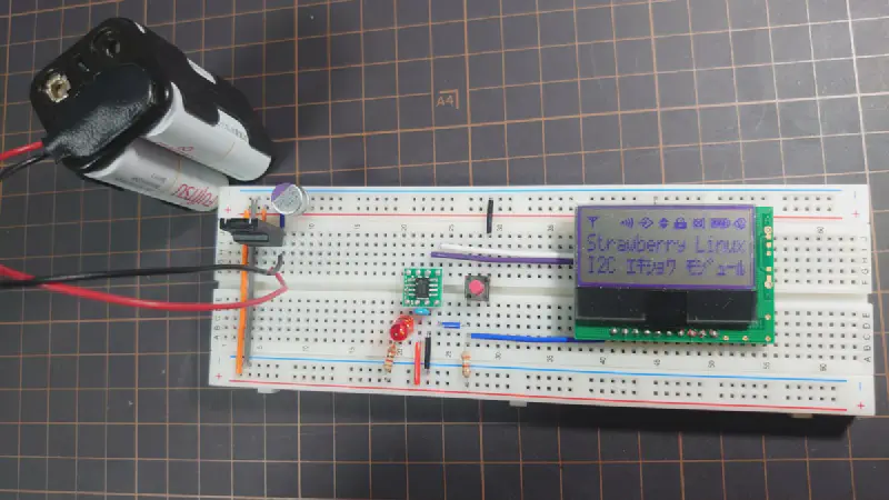
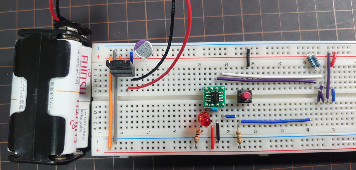
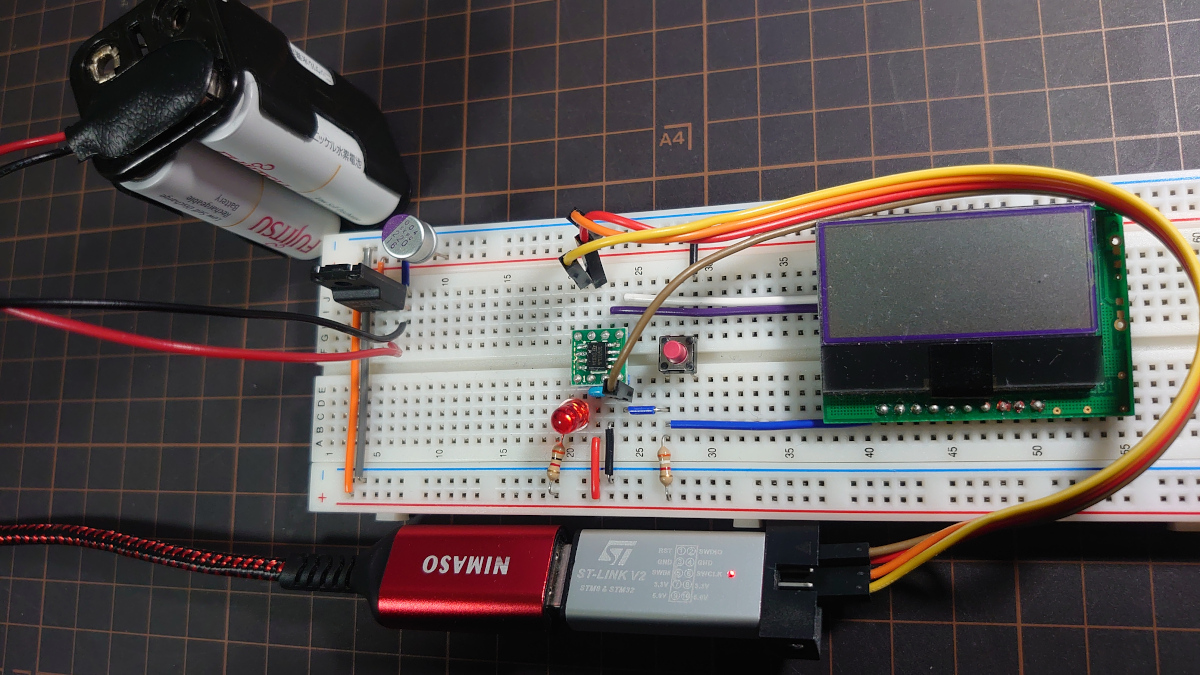
ブレッドボードで配線する
ニッケル水素電池(1.2V)を4直列から3端子レギュレータNJU7223F33で3.3V電源を作る。
LCDの下はこうで
これでOK
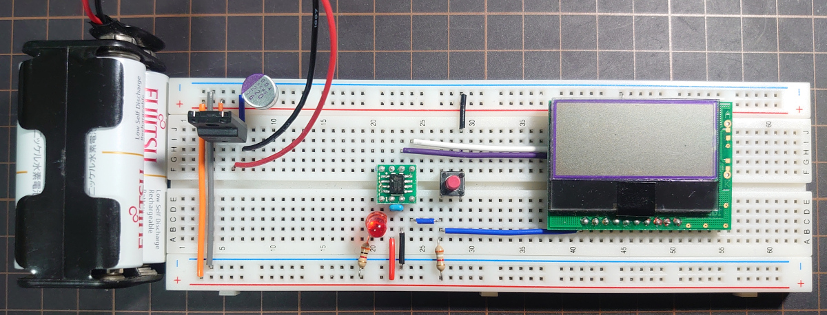
まだ何も起きない。(あたりまえ)
STM32マイコンにプログラムを書き込まないと。
STM32CubeIDEでプログラムを書く
STM32CubeIDEのバージョンは
プロジェクトを新規作成
File -> New でSTM32 プロジェクトを選択して,
MCU: STM32G031J6, Cプロジェクトを選んで新規作成する。
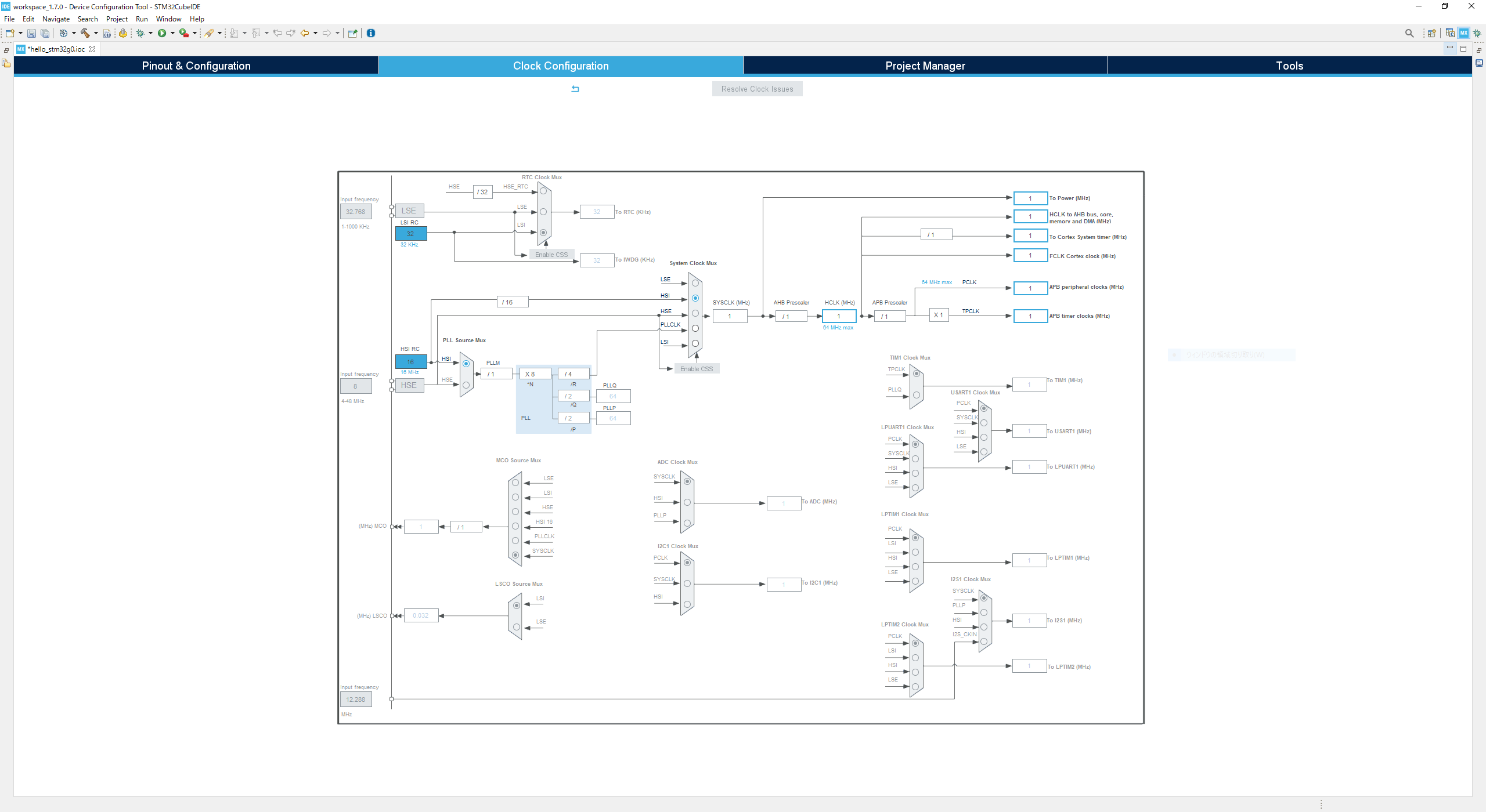
クロックはHSI RC発振 (16MHz)を16分周して生成した1MHzをSYSCLKにしておけばいいんとちゃいますか。
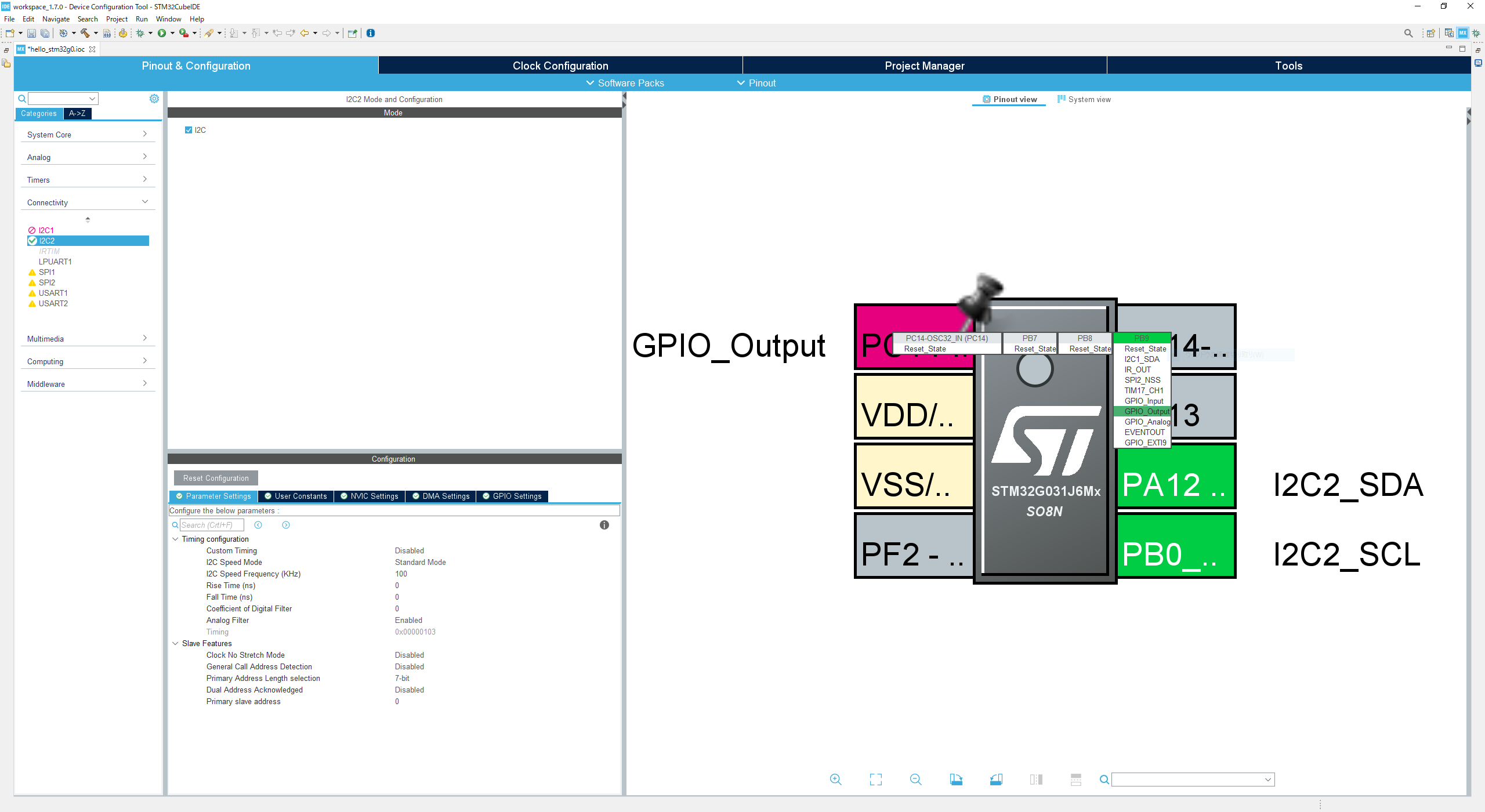
- PB9をGPIO_Output
- I2C2を100kHzで駆動
この設定でCubeIDEに生成してもらったmain.cの USER CODE BEGIN ~ END の間をいじる。(それ以外に書いたものは消されるよ)
エディタに慣れないしC++を使いたくなるがそれはとにかく,
液晶モジュールのAVR用サンプルコードを見ながらちょいちょいと書いてみる。
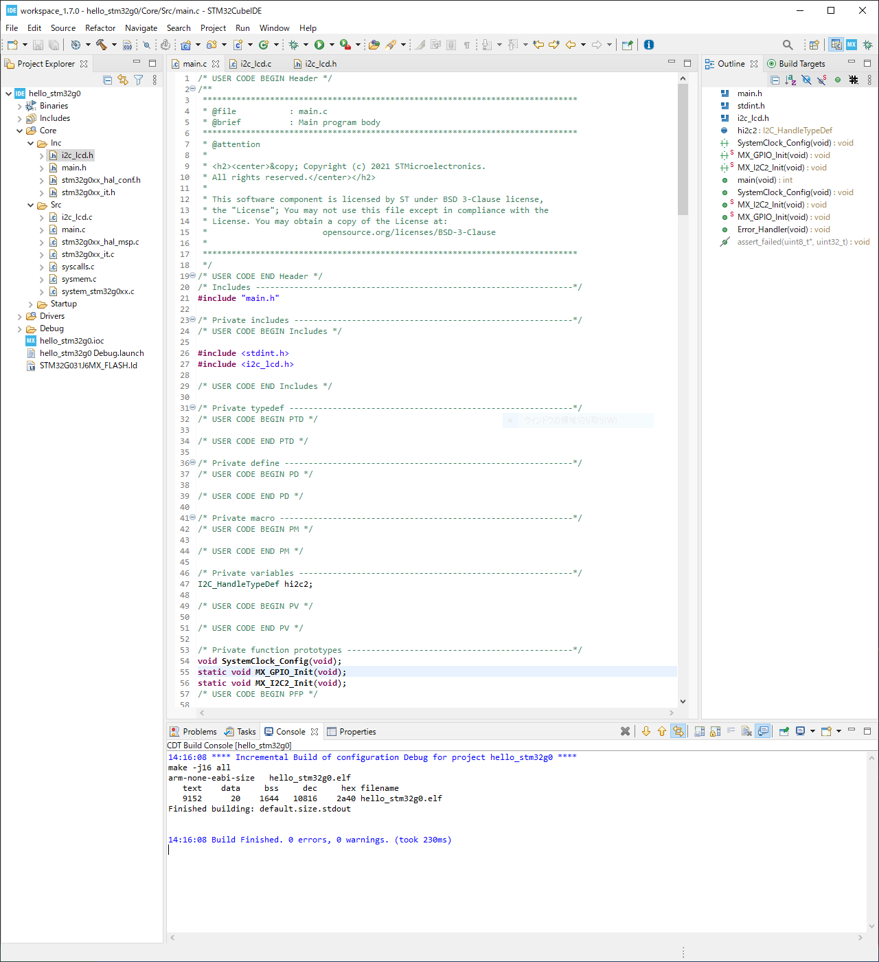
Core/Src/main.c
| |
Core/Src/i2c_lcd.c
| /* | |
| * i2c_lcd.c | |
| * | |
| * Created on: 2021/11/22 | |
| * Author: Akihiro Yamamoto | |
| * | |
| * Copyright 2021 Akihiro Yamamoto | |
| * Licensed under the Apache License, Version 2.0 | |
| * | |
| */ | |
| #include "main.h" | |
| #include <stdint.h> | |
| #include <string.h> | |
| #include <i2c_lcd.h> | |
| #if __STDC_VERSION__ >= 199901L | |
| #else | |
| #error ISO C99 or newer compiler required. | |
| #endif | |
| #define ARRAY_SIZE(a) (sizeof(a) / sizeof(a[0])) | |
| #define I2C_LCD_TIMEOUT ((uint8_t)100) | |
| #define I2C_LCD_ADDRESS ((uint8_t)0x3e) | |
| #define I2C_LCD_CBYTE_COMMAND ((uint8_t)0x00) | |
| #define I2C_LCD_CBYTE_DATA ((uint8_t)0x40) | |
| #define I2C_LCD_CBYTE_CONTINUATION ((uint8_t)0x80) | |
| typedef struct { | |
| icon_code_t icon_code; | |
| uint8_t addr; | |
| uint8_t bit; | |
| } icon_t; | |
| // @formatter:off | |
| static const icon_t I2C_LCD_ICON_DATA[13] = { | |
| { I2C_LCD_ICON_a, 0x00, 0b10000 }, // S1 ANTENNA | |
| { I2C_LCD_ICON_b, 0x02, 0b10000 }, // S11 TEL | |
| { I2C_LCD_ICON_c, 0x04, 0b10000 }, // S21 | |
| { I2C_LCD_ICON_d, 0x06, 0b10000 }, // S31 | |
| { I2C_LCD_ICON_e, 0x07, 0b10000 }, // S36 UP ARROW | |
| { I2C_LCD_ICON_f, 0x07, 0b01000 }, // S37 DOWN ARROW | |
| { I2C_LCD_ICON_g, 0x09, 0b10000 }, // S46 LOCKED | |
| { I2C_LCD_ICON_h, 0x0b, 0b10000 }, // S56 | |
| { I2C_LCD_ICON_i, 0x0d, 0b10000 }, // S66 BATTERY LOW | |
| { I2C_LCD_ICON_j, 0x0d, 0b01000 }, // S67 BATTERY MID | |
| { I2C_LCD_ICON_k, 0x0d, 0b00100 }, // S68 BATTERY HIGH | |
| { I2C_LCD_ICON_l, 0x0d, 0b00010 }, // S69 BATTERY FRAME | |
| { I2C_LCD_ICON_m, 0x0f, 0b10000 }, // S76 | |
| }; | |
| // @formatter:on | |
| // @formatter:off | |
| inline static void i2c_lcd_wait_a_moment() { | |
| asm("NOP"); asm("NOP"); asm("NOP"); asm("NOP"); asm("NOP"); | |
| asm("NOP"); asm("NOP"); asm("NOP"); asm("NOP"); asm("NOP"); | |
| // 10 | |
| asm("NOP"); asm("NOP"); asm("NOP"); asm("NOP"); asm("NOP"); | |
| asm("NOP"); asm("NOP"); asm("NOP"); asm("NOP"); asm("NOP"); | |
| // 20 | |
| asm("NOP"); asm("NOP"); asm("NOP"); asm("NOP"); asm("NOP"); | |
| asm("NOP"); asm("NOP"); asm("NOP"); asm("NOP"); asm("NOP"); | |
| // 30 | |
| asm("NOP"); asm("NOP"); asm("NOP"); asm("NOP"); asm("NOP"); | |
| asm("NOP"); asm("NOP"); asm("NOP"); asm("NOP"); asm("NOP"); | |
| // 40 | |
| asm("NOP"); asm("NOP"); asm("NOP"); asm("NOP"); asm("NOP"); | |
| asm("NOP"); asm("NOP"); asm("NOP"); asm("NOP"); asm("NOP"); | |
| // 50 | |
| } | |
| // @formatter:on | |
| void i2c_lcd_init(I2C_HandleTypeDef *hi2c) { | |
| uint8_t contrast = 0b101000; | |
| /* first step */ | |
| { | |
| // @formatter:off | |
| uint8_t sequence[] = { | |
| 0b00111000, // function set | |
| 0b00111001, // function set | |
| 0b00010100, // interval osc | |
| 0b01110000 | (contrast & 0xf), // contrast Low | |
| 0b01011100 | ((contrast >> 4) & 0x3), // contast High/icon/power | |
| 0b01101100, // follower control | |
| }; | |
| // @formatter:on | |
| i2c_lcd_send_commands(hi2c, ARRAY_SIZE(sequence), sequence); | |
| } | |
| HAL_Delay(200); | |
| /* second step */ | |
| { | |
| // @formatter:off | |
| uint8_t sequence[] = { | |
| 0b00111000, // function set | |
| 0b00001100, // Display On | |
| 0b00000001, // Clear Display | |
| }; | |
| // @formatter:on | |
| i2c_lcd_send_commands(hi2c, ARRAY_SIZE(sequence), sequence); | |
| } | |
| HAL_Delay(2); | |
| } | |
| static void master_transmit(I2C_HandleTypeDef *hi2c, uint8_t cbyte, size_t size, uint8_t data[size]) { | |
| size_t i; | |
| uint8_t buff[size * 2]; | |
| for (i = 0; i < (size - 1); ++i) { | |
| buff[i * 2 + 0] = I2C_LCD_CBYTE_CONTINUATION | cbyte; | |
| buff[i * 2 + 1] = data[i]; | |
| } | |
| buff[i * 2 + 0] = cbyte; | |
| buff[i * 2 + 1] = data[i]; | |
| HAL_I2C_Master_Transmit(hi2c, I2C_LCD_ADDRESS << 1, buff, ARRAY_SIZE(buff), | |
| I2C_LCD_TIMEOUT); | |
| i2c_lcd_wait_a_moment(); | |
| } | |
| void i2c_lcd_send_commands(I2C_HandleTypeDef *hi2c, size_t size, | |
| uint8_t cmds[size]) { | |
| master_transmit(hi2c, I2C_LCD_CBYTE_COMMAND, size, cmds); | |
| } | |
| void i2c_lcd_send_data(I2C_HandleTypeDef *hi2c, size_t size, uint8_t data[size]) { | |
| master_transmit(hi2c, I2C_LCD_CBYTE_DATA, size, data); | |
| } | |
| void i2c_lcd_puts(I2C_HandleTypeDef *hi2c, char *s) { | |
| i2c_lcd_send_data(hi2c, strlen(s), (uint8_t*) s); | |
| } | |
| void i2c_lcd_show_icon(I2C_HandleTypeDef *hi2c, icon_code_t bitflag) { | |
| uint8_t buff[16] = { 0 }; | |
| for (uint8_t i = 0; i < ARRAY_SIZE(I2C_LCD_ICON_DATA); ++i) { | |
| const icon_t *p = &I2C_LCD_ICON_DATA[i]; | |
| if (bitflag & p->icon_code) { | |
| buff[p->addr] |= p->bit; | |
| } | |
| } | |
| for (uint8_t addr = 0; addr < ARRAY_SIZE(buff); ++addr) { | |
| // @formatter:off | |
| uint8_t cmds[] = { | |
| 0b00111001, // function set | |
| 0b01000000 | addr, // set icon address | |
| }; | |
| // @formatter:on | |
| i2c_lcd_send_commands(hi2c, ARRAY_SIZE(cmds), cmds); | |
| i2c_lcd_send_datum(hi2c, buff[addr]); | |
| } | |
| } |
Core/Inc/i2c_lcd.h
| /* | |
| * i2c_lcd.h | |
| * | |
| * Created on: 2021/11/22 | |
| * Author: Akihiro Yamamoto | |
| * | |
| * Copyright 2021 Akihiro Yamamoto | |
| * Licensed under the Apache License, Version 2.0 | |
| * | |
| */ | |
| #ifndef INC_I2C_LCD_H_ | |
| extern void i2c_lcd_init(I2C_HandleTypeDef *i2c); | |
| extern void i2c_lcd_send_commands(I2C_HandleTypeDef *hi2c, size_t size, | |
| uint8_t cmds[size]); | |
| inline static void i2c_lcd_send_command(I2C_HandleTypeDef *hi2c, uint8_t cmd) { | |
| i2c_lcd_send_commands(hi2c, 1, &cmd); | |
| } | |
| extern void i2c_lcd_send_data(I2C_HandleTypeDef *hi2c, size_t size, | |
| uint8_t data[size]); | |
| inline static void i2c_lcd_send_datum(I2C_HandleTypeDef *hi2c, uint8_t datum) { | |
| i2c_lcd_send_data(hi2c, 1, &datum); | |
| } | |
| extern void i2c_lcd_puts(I2C_HandleTypeDef *hi2c, char *s); | |
| inline static void i2c_lcd_clear_display(I2C_HandleTypeDef *hi2c) { | |
| i2c_lcd_send_command(hi2c, 0b00000001); | |
| HAL_Delay(1); | |
| } | |
| inline static void i2c_lcd_return_home(I2C_HandleTypeDef *hi2c) { | |
| i2c_lcd_send_command(hi2c, 0b00000010); | |
| HAL_Delay(1); | |
| } | |
| inline static void i2c_lcd_set_ddram_address(I2C_HandleTypeDef *hi2c, | |
| uint8_t addr) { | |
| i2c_lcd_send_command(hi2c, 0x80 | (addr & 0x7f)); | |
| } | |
| typedef uint16_t icon_code_t; | |
| #define I2C_LCD_ICON_a ((icon_code_t)(1<<12)) | |
| #define I2C_LCD_ICON_b ((icon_code_t)(1<<11)) | |
| #define I2C_LCD_ICON_c ((icon_code_t)(1<<10)) | |
| #define I2C_LCD_ICON_d ((icon_code_t)(1<<9)) | |
| #define I2C_LCD_ICON_e ((icon_code_t)(1<<8)) | |
| #define I2C_LCD_ICON_f ((icon_code_t)(1<<7)) | |
| #define I2C_LCD_ICON_g ((icon_code_t)(1<<6)) | |
| #define I2C_LCD_ICON_h ((icon_code_t)(1<<5)) | |
| #define I2C_LCD_ICON_i ((icon_code_t)(1<<4)) | |
| #define I2C_LCD_ICON_j ((icon_code_t)(1<<3)) | |
| #define I2C_LCD_ICON_k ((icon_code_t)(1<<2)) | |
| #define I2C_LCD_ICON_l ((icon_code_t)(1<<1)) | |
| #define I2C_LCD_ICON_m ((icon_code_t)(1<<0)) | |
| extern void i2c_lcd_show_icon(I2C_HandleTypeDef *hi2c, icon_code_t bitflag); | |
| #endif /* INC_I2C_LCD_H_ */ |
プロジェクトのビルド
Ctrl + B でビルド。
| |
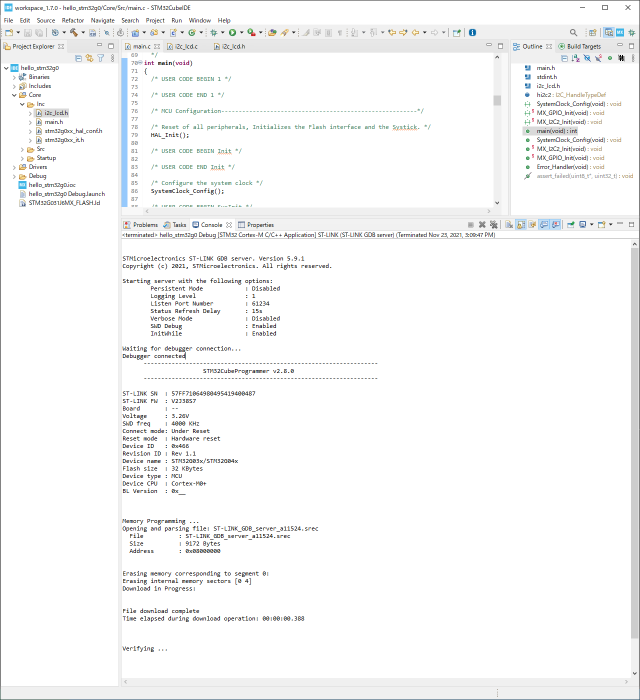
中華ST-Linkでプログラミング
Nucleoボードを持っているからそのST-Linkを使えばいいのだけれど,
中華ST-Linkを使ってみたかった。
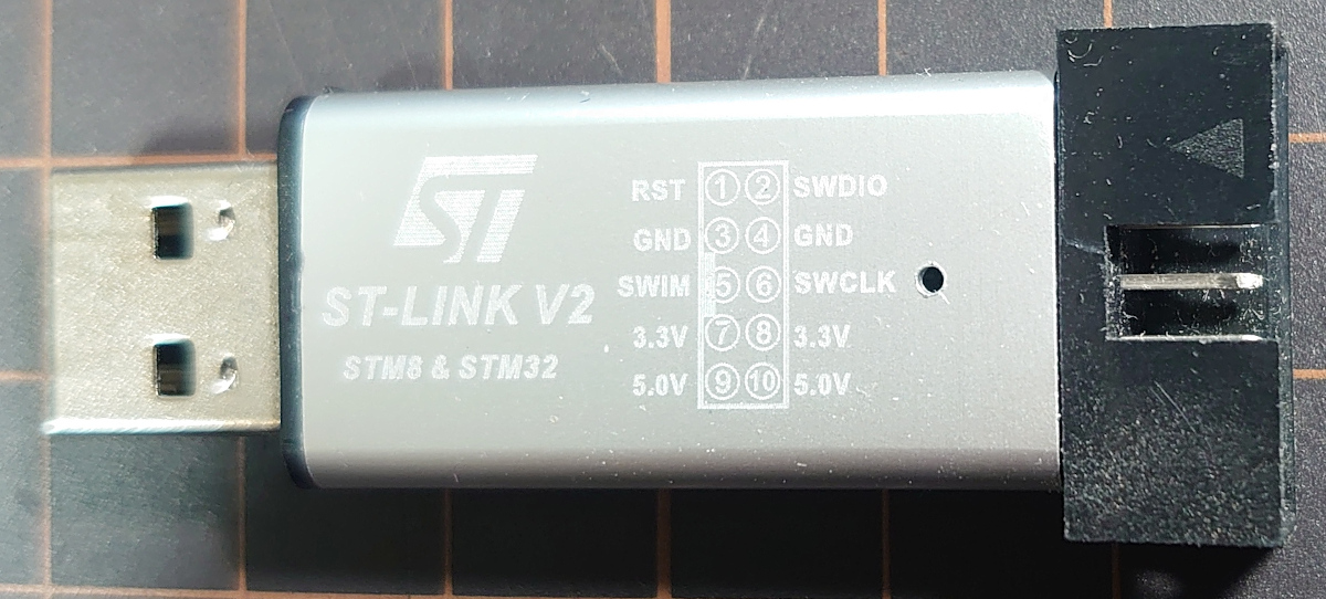
STM32G031J6M6の
- pin 3 (VSS) を ST-Link のGNDピン(#4)と接続
- pin 4 (NRST) を ST-Link のRSTピン(#1)と接続
- pin 7 (SWDIO) を ST-Link のSWDIOピン(#2)と接続
- pin 8 (SWCLK) を ST-Link のSWCLKピン(#6)と接続 ST-Link のRSTピンはつながなくても書き込みの時に手動でリセットボタンを押してもいい。
準備ができたらCubeIDEに戻ってRun -> Runする。
ファームウエアのアップデートが要求されるかも知れないけど何とかして。
| |
おつかれした!
ここまで済ませたら, プログラマー(書き込み器)は不要になる。
