M5Stack Core2にBME280センサーを接続して温度/湿度/気圧の測定をしてみる。
使うもの
BME280モジュールの仕様を確認する
BME280モジュールの電源電圧はDC 1.8~3.3V となっていて
消費電流はBME280のデーターシートを確認すると
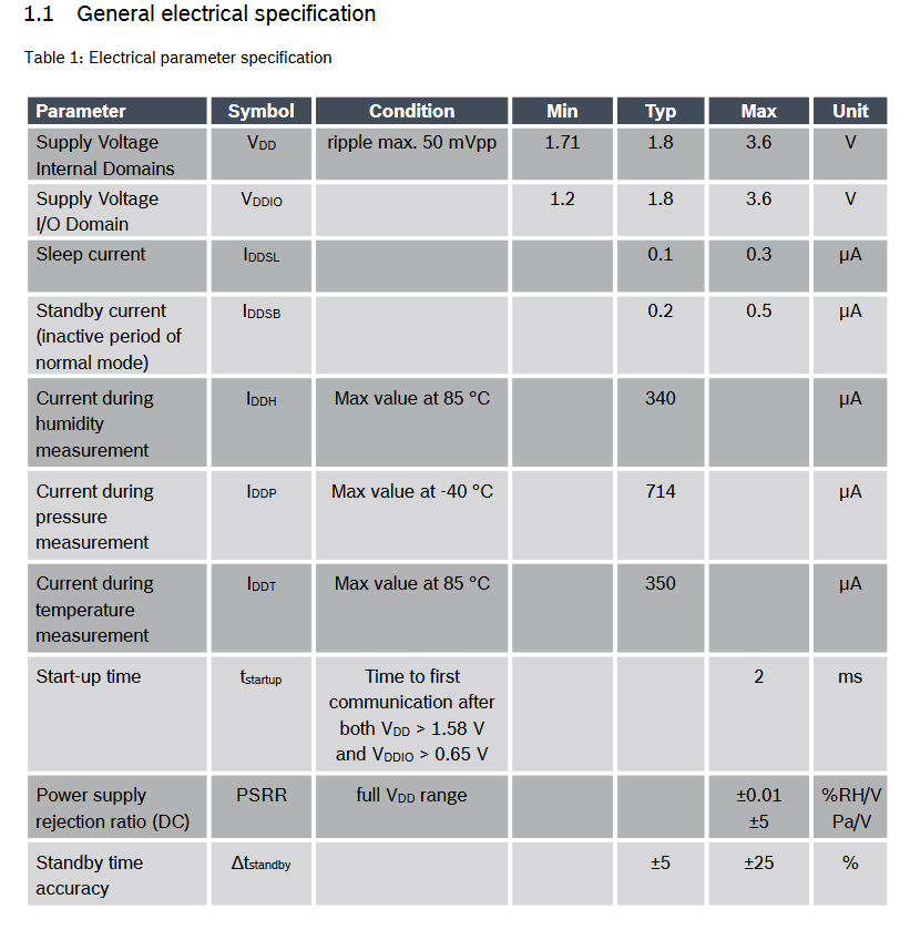
Maxの記載がないけどTypの電流を見るとIDDP=714μAだって。
BME280モジュールにデカップリングコンデンサとして(0.1μF)C1, C2が2つ接続されているから
電流が平準化されて電源ピンにこんなにたくさん流れないだろうけど。
3.3Vを用意する
1mA以下のたいした電流が流れないようなのでM5Stack Core2のGrove端子電圧5Vから抵抗分圧で3.3Vを作ることにする。
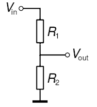
$$ V_{in} : V_{out} = (R_1 + R_2) : R_2 \tag1 $$
(1)式は
$$ \frac{V_{in}}{V_{out}} = \frac{R_1 + R_2}{R_2} \tag2 $$
なので (2)式に今回は
- $V_{in} = 5.0\mathrm{V}$
- $V_{out} = 3.3\dot{3}\mathrm{V}$ (つまり1/3。このくらいの差は無害なので)
$$ \frac{V_{in}}{V_{out}} = \frac{5.0}{3.3\dot{3}} \\ $$ を代入して
$$ \begin{aligned} \frac{R_1 + R_2}{R_2} &= \frac{5.0}{3.3\dot{3}} \\ &= \frac{5.0}{3.3\dot{3}} \times \frac{3}{3} \\ &= \frac{15}{10} \end{aligned} $$
$$ \therefore \frac{R_1 + R_2}{R_2} = \frac{3}{2} \tag3 $$
(3)式の両辺をたすき掛けして
$$ \begin{aligned} 3 R_2 &= 2 R_1 + 2 R_2 \\ 3 R_2 - 2 R_2 &= 2 R_1 \\ R_2 &= 2 R_1 \end{aligned} $$
下側の抵抗器$R_2$は上側の抵抗器$R_1$と同じ値の抵抗器を2直列に接続したものと同じ値なので, 同じ値の抵抗器$R$を3直列に接続して分圧することにする。
つまりこうする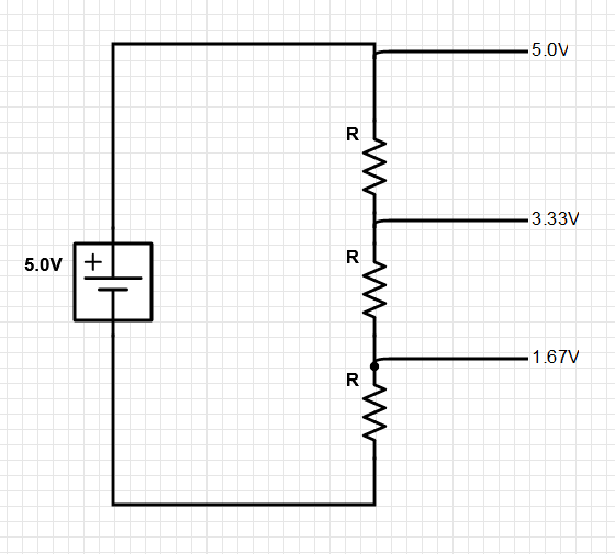
抵抗値を決める
R1 および R2 に比較して RL が極めて大きい場合のみ、分圧回路を電圧源として使うことができる。 しかし、そうすると電力のほとんどを分圧回路で消費してしまうため、このような手法はあまり用いられない。
分圧抵抗の値には負荷抵抗値に比較してあまり高い抵抗値を使えないので, 分圧回路に無負荷電流$I_{idle}$を5mAくらい流しておくとするとその抵抗値Rは $$ \begin{aligned} 3R &= \frac{V_{in}}{I_{idle}} \\ &= \frac{5.0}{5 \times 10^{-3}} \\ &= \frac{5.0}{5} \times \frac{1}{10^{-3}} \\ &= \frac{5.0}{5} \times 10 ^3 \\ &= 1 \times 10 ^3 \\ &= 1000 \Omega \end{aligned} $$
となって抵抗値Rは $$ R = \frac{1000}{3} = 333.\dot{3} \Omega $$
そんな抵抗値の金属皮膜抵抗器を持ってなかったので,
手持ちの精度1%, 1/4Wの金属皮膜抵抗器 $1 \mathrm{k\Omega}$ で代用しようと思う。
その場合の無負荷電流は
$$ \begin{aligned} I_{idle} &= \frac{V_{in}}{3R} \\ &= \frac{5.0}{3 \times 1000} \\ &= \frac{5.0}{3000} \\ &= \frac{5.0}{3} \times 10^{-3} \\ &= 1.67 \times 10^{-3} \\ &= 1.67 \mathrm{mA} \end{aligned} $$
これでも何とかなるだろう。
抵抗器の発熱はほぼ無負荷電流によるので
各抵抗器で消費される消費電力P(W)を求めると
$P = VI$ に $V = IR$を代入して
$$
\begin{aligned}
P &= V \cdot I \\
&= I \cdot R \cdot I \\
&= I^2 \cdot R
\end{aligned}
$$
だから $$ \begin{aligned} P &= \left( \frac{5.0}{3000} \right) ^2 \times 1000 \\ &= \frac{5.0^2}{3^2 \times 1000^2} \times 1000 \\ &= \frac{25}{9 \times (10^3)^2} \times 1000 \\ &= \frac{25}{9} \times \frac{1}{10^6} \times 1000 \\ &= 2.78 \times \frac{1000}{10^6} \\ &= 2.78 \times 10^{-3} \\ &= 2.78 \mathrm{mW} \end{aligned} $$
この抵抗器の許容電力は $1/4 \mathrm{W} = 0.25 \mathrm{W} = 250 \mathrm{mW}$ だから 無視できるくらいの発熱量。
BME280モジュールをM5Stack用ミニプロトユニットに収める
M5Stack用ミニプロトユニットのGrove端子と
| M5Stack用ミニプロトユニットのGrove端子 | 色 | 機能 |
|---|---|---|
| GND | 黒 | GND |
| 5V | 赤 | 5V |
| X | 黄 | SDA |
| X | 白 | SCL |
5V -> 3.3V分圧回路を間にはさんでBME280モジュールを接続する。
| BME280モジュール | BME280モジュール基板上で接続 | M5Stack用ミニプロトユニット |
|---|---|---|
| Vio | — | 3.3V |
| Vcore | 3.3V | - |
| GND | — | GND |
| CSB | 3.3V | - |
| SDI | — | SDA |
| SCK | — | SCL |
| SDO | GND | - |
それぞれはんだ付けして配線したらM5Stack用ミニプロトユニットに収める。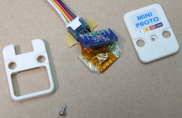
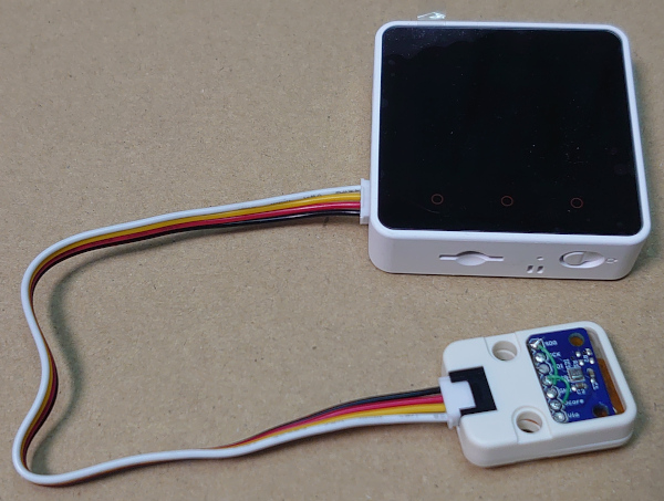
BME280モジュールとM5Stackを接続する
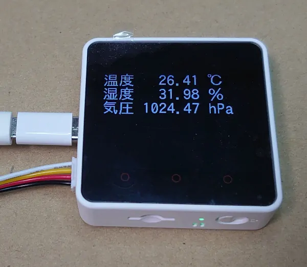
BME280モジュールで温度/湿度/気圧測定
試運転のためのソフトウェアを用意する。
前回に続いてLovyanGFXとAdafruit BME280ライブラリを使用させてもらいました。
; PlatformIO Project Configuration File
;
;   Build options: build flags, source filter
;   Upload options: custom upload port, speed and extra flags
;   Library options: dependencies, extra library storages
;   Advanced options: extra scripting
;
; Please visit documentation for the other options and examples
; https://docs.platformio.org/page/projectconf.html

[env:m5stack-core2]
platform = espressif32
board = m5stack-fire
framework = arduino
monitor_speed = 115200
lib_deps =
	https://github.com/m5stack/M5Core2.git
	lovyan03/LovyanGFX
	adafruit/Adafruit BME280 Library@^2.1.2
adafruit/Adafruit Unified Sensor@^1.1./*
* Copyright 2020 Akihiro Yamamoto
*/
#include <M5Core2.h>
#include <Adafruit_Sensor.h>
#include <Adafruit_BME280.h>
#define LGFX_M5STACK_CORE2
#include <LovyanGFX.hpp>
static LGFX lcd;
static const uint8_t BME280_I2C_ADDRESS = 0x76;
static Adafruit_BME280 bme280;
static Adafruit_Sensor *bme280_temperature = bme280.getTemperatureSensor();
static Adafruit_Sensor *bme280_pressure = bme280.getPressureSensor();
static Adafruit_Sensor *bme280_humidity = bme280.getHumiditySensor();
const unsigned long background_color = 0x000000U;
const unsigned long message_text_color = 0xFFFFFFU;
void releaseEvent(Event &e)
{
}
void setup()
{
M5.begin(true, true, true, true);
M5.Buttons.addHandler(releaseEvent, E_RELEASE);
//
lcd.init();
lcd.setFont(&fonts::lgfxJapanGothic_36);
lcd.setTextColor(message_text_color, background_color);
//
while (!bme280.begin(BME280_I2C_ADDRESS))
{
lcd.printf("BME280センサが見つかりません。");
while (1)
{
delay(10);
}
}
//
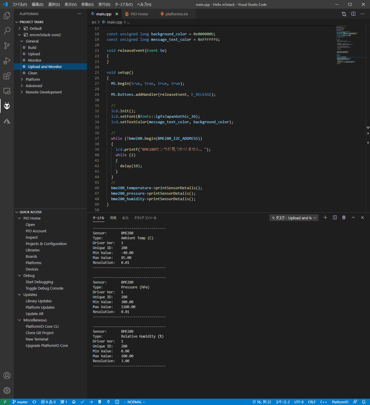
bme280_temperature->printSensorDetails();
bme280_pressure->printSensorDetails();
bme280_humidity->printSensorDetails();
}
void loop()
{
M5.update();
//
sensors_event_t temperature_event;
sensors_event_t humidity_event;
sensors_event_t pressure_event;
bme280_temperature->getEvent(&temperature_event);
bme280_humidity->getEvent(&humidity_event);
bme280_pressure->getEvent(&pressure_event);
lcd.setCursor(0, 0);
lcd.printf("温度 %7.2f ℃\n", temperature_event.temperature);
lcd.printf("湿度 %7.2f %\n", humidity_event.relative_humidity);
lcd.printf("気圧 %7.2f hPa\n", pressure_event.pressure);
delay(1000);
}
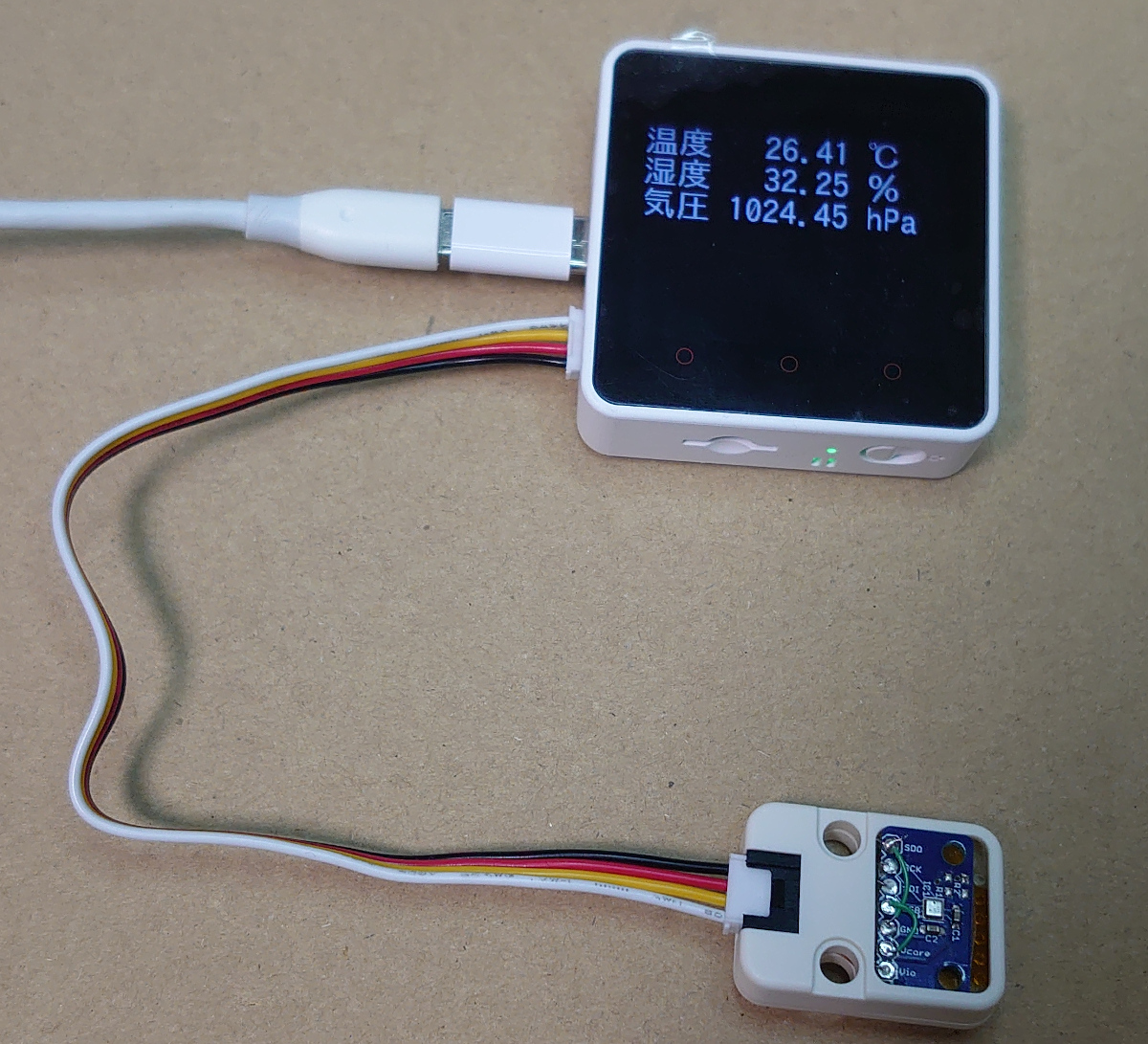
BME280はラズパイで使った経験があるし, さらに便利なライブラリがあるから
ディスプレイに日本語表示をするのに苦労せずすんなりと完成した。
コメント