ダイキンエアコンのリモコン信号を解析してみた。
赤外線リモコン信号受信用ハードウェア
前にしたようにラズパイを使ってもよいが, 今回はこれ「Seeeduino XIAO」を使ってみることにする。
- スイッチサイエンス https://www.switch-science.com/catalog/6335/
- 秋月電子通商 (通販コード M-15178) http://akizukidenshi.com/
等々。
財布に優しいのでこの用途にはこれがベストでなかろうかと。
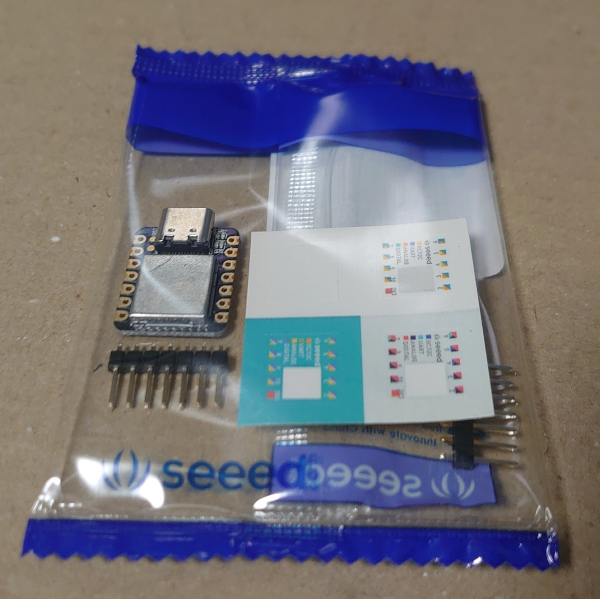
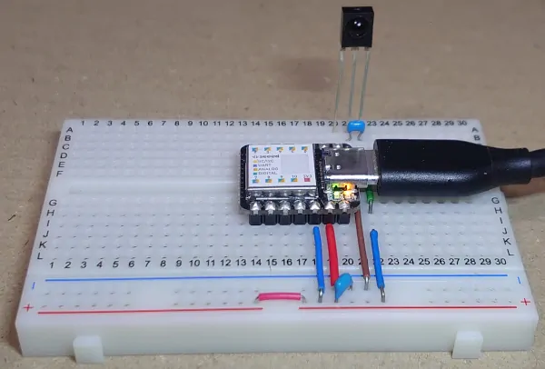
ピンをはんだ付けしてブレッドボードへ。
CircuitPython on Seeeduino XIAO
今回はCircuitPythonを使うことにする。
seeedstudioのWiki のページに従って Seeeduino XIAO に CircuitPython を入れる。
main.py
これをGitHubからダウンロードして, USBを接続したときに出てくる"CIRCUITPY"というドライブのルートフォルダに保存する。
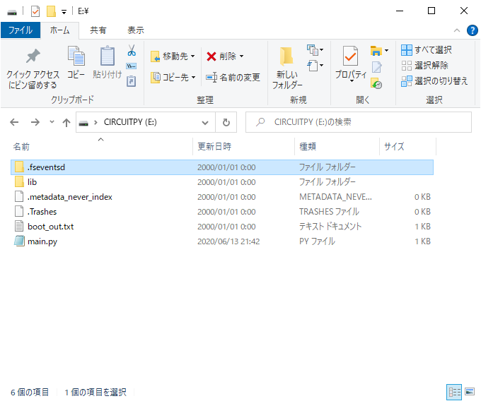
ここまでうまくできていればオンボードのLEDが点滅している。
赤外線リモコン信号受信
PC - Seeeduino XIAO間の通信はUSBシリアルなので, シリアルコンソールソフトウェアが必要です。 今回はArduino IDEとRLoginを例に使います。
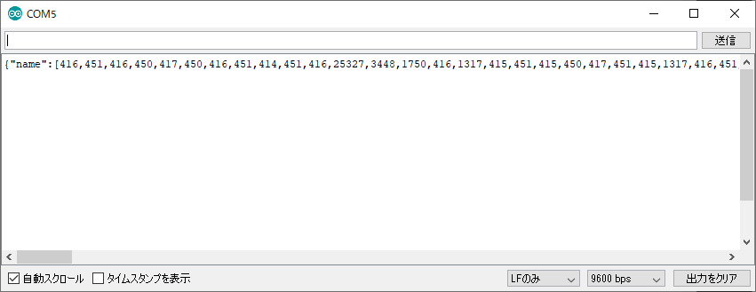
Arduino IDEの場合
ツール - シリアルポート メニューからCOM5を選んで(COM番号は状況によってまちまち),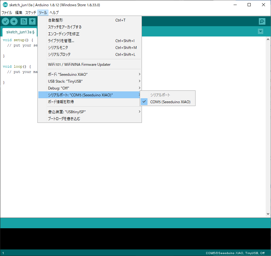
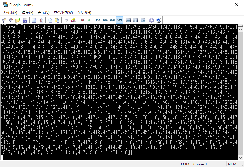
RLoginの場合
RLoginの場合でもこのように受け取れる。
受信したリモコン信号
{"name":[417,448,418,450,417,450,417,449,418,448,417,25329,3450,1747,418,1315,419,446,419,449,417,450,417,1315,418,449,417,449,417,449,417,450,417,1314,418,450,417,1315,417,1315,418,448,418,1315,418,1315,417,1315,418,1315,417,1315,418,450,417,448,419,1312,419,449,417,449,417,451,416,449,419,448,417,449,417,450,417,448,419,448,417,449,417,1316,417,450,416,1314,419,448,418,449,417,449,418,1314,418,1314,419,449,417,450,417,448,419,447,418,450,417,448,419,448,417,449,417,449,418,448,418,449,418,449,417,448,419,448,417,449,418,449,417,1315,418,1314,418,1315,418,448,419,1313,419,448,419,1313,419,1313,420,34665,3450,1748,418,1314,419,447,418,450,416,450,417,1316,416,450,418,448,417,449,418,449,417,1315,418,449,418,1315,417,1315,417,451,416,1316,417,1314,418,1314,418,1316,416,1316,417,450,417,450,417,1313,418,451,416,449,417,449,418,449,416,450,417,449,417,450,416,449,417,450,416,451,416,449,419,1314,418,448,417,449,417,451,416,449,418,1317,416,450,415,450,417,449,418,448,417,450,416,450,417,451,416,448,417,450,417,449,417,450,417,450,417,449,418,448,417,453,414,449,417,449,417,450,416,450,416,1316,418,449,417,1315,417,449,418,1315,418,449,417,34670,3449,1750,416,1316,417,451,416,449,416,450,417,1315,418,450,416,450,415,451,417,449,417,1316,416,450,418,1315,416,1316,417,449,418,1315,418,1315,417,1316,417,1315,417,1315,418,450,416,450,417,1316,416,454,412,450,416,451,416,450,416,450,416,450,416,451,416,451,417,448,417,450,416,449,418,450,417,448,417,450,417,450,416,450,416,450,417,450,416,1317,416,1316,416,450,416,1317,417,1315,417,1316,417,449,418,448,417,452,414,451,416,1316,416,1316,417,450,416,1316,417,449,418,450,417,449,416,450,417,450,417,450,416,450,416,451,415,450,419,448,416,1316,417,1316,417,1315,418,1317,416,450,417,449,417,1315,417,450,416,450,420,448,415,450,416,450,417,450,416,450,416,450,417,449,418,1315,417,451,416,449,417,1316,416,451,416,450,416,451,415,1316,417,451,416,1316,416,450,418,450,415,450,416,451,416,451,416,449,417,450,416,450,417,450,416,450,416,450,416,1316,417,1317,417,447,418,450,416,451,416,451,416,449,416,450,417,450,417,449,416,450,416,452,414,451,416,450,416,451,415,451,416,451,415,450,416,451,416,1317,416,451,415,451,416,451,415,452,414,451,415,1317,417,1316,416,451,416,451,416,450,415,453,414,451,415,451,416,451,415,452,414,452,415,450,417,451,416,451,414,451,416,451,416,451,414,451,416,451,415,451,416,1317,416,451,415,1317,416,1316,417,1316,416,451,416]}解析結果
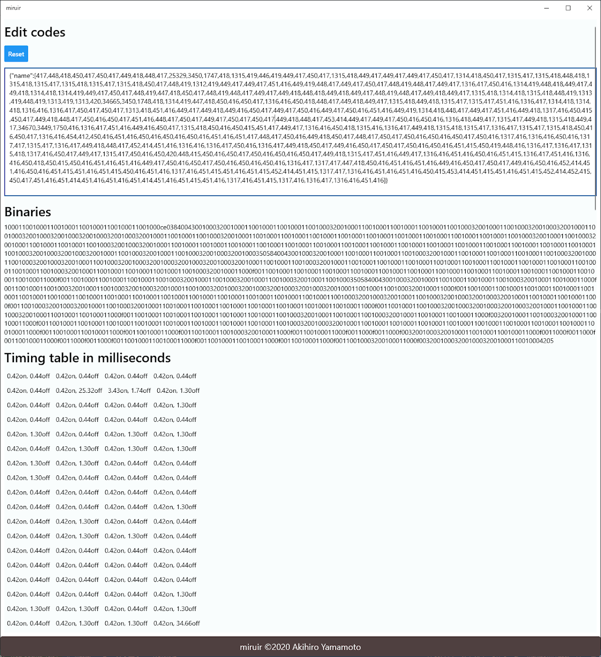
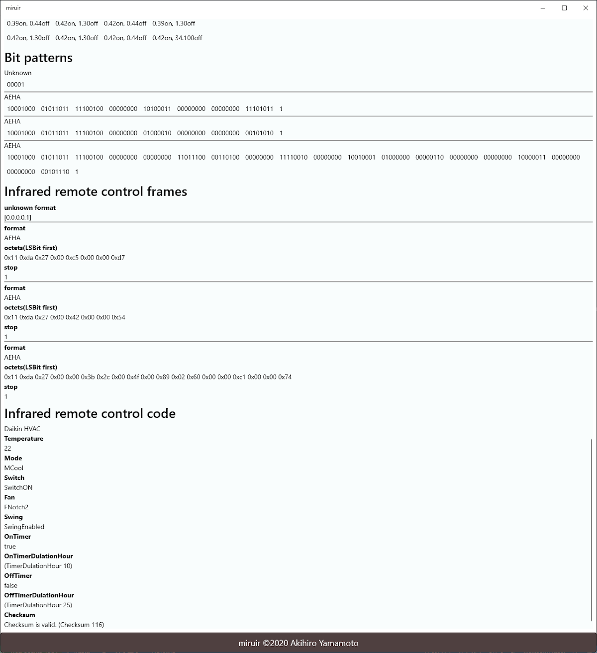
今回作ったアプリケーションで解析すると
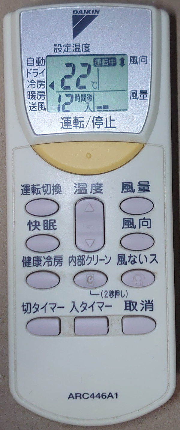
ダイキンエアコン, 温度22℃, 冷房, スイッチON, 風向上下, 風量2, オンタイマー10時間
(リモコン画像が違うかアプリケーションがバグっているかもしれない)
赤外線リモコン信号の解析アプリケーション
赤外線リモコン信号の解析アプリケーション のページで予告した通り赤外線リモコン信号の解析アプリケーションを分割して新しく作った。
https://github.com/ak1211/miruir
これ(UWP版)もWebアプリ版も同じ解析エンジンなので当然同じように使えますよ。
使いやすい方で試してください。
ダイキン工業製エアコンの赤外線リモコン信号の解析
信号解析は以下の情報を参考にしました。
https://github.com/blafois/Daikin-IR-Reverse
Timer
There are 2 times: timer for Power On and timer for Power Off. The type of timer is coded at offset 5
The timer delay position and coding defers depending of timer type.
For Timer ON, the delay is on offset 0a and 0b, with the following coding:
Few examples:
PLAINTEXT4H = 4 * 60 = 240 minutes = 0x00f0. This will be coded as f0 00 5H = 5 * 60 = 300 minutes = 0x012c. This will be coded as 2c 01In Java, this can be decoded using the following code snippet:
JAVAint timerDuration = (0x100 * message[0xb] + message[0xa]) / 60;For Timer OFF, the delay is on offset 0b and 0c, with the following coding:
Few examples:
PLAINTEXT1H = 1 * 60 = 60 minutes = 0x003C. This will be coded as c6 03 5H = 5 * 60 = 300 minutes = 0x012c. This will be coded as 2c 01In Java, this can be decoded using the following code snippet:
JAVAint timerDuration = ((message[0xc] << 4) | (message[0xb] >> 4)) / 60;
このタイマー時間の抽出部分がよくわかっていない。(Java言語むつかしいので)
とりあえず今は こんなふう に適当にお茶を濁すことにする。
デコード関数
資料に対応するデコード関数がこれね。
構造そのまま記述したから見ればわかるだろうけど,
これは11, da, 27, 00, 00(16進数)から始まる第3フレームをデコードする。
  decode :: Array BitStream -> Maybe DaikinHvac
  decode bitstreams = do
    b_0 <- toLsbFirst <$> bitstreams !! 0
    b_1 <- toLsbFirst <$> bitstreams !! 1
    b_2 <- toLsbFirst <$> bitstreams !! 2
    b_3 <- toLsbFirst <$> bitstreams !! 3
    b_4 <- toLsbFirst <$> bitstreams !! 4
    b_5 <- (unBitOrder <<< toLsbFirst) <$> bitstreams !! 5
    b_6 <- (unBitOrder <<< toLsbFirst) <$> bitstreams !! 6
    b_8 <- (unBitOrder <<< toLsbFirst) <$> bitstreams !! 8
    b10 <- (unBitOrder <<< toLsbFirst) <$> bitstreams !! 10
    b11 <- (unBitOrder <<< toLsbFirst) <$> bitstreams !! 11
    b12 <- (unBitOrder <<< toLsbFirst) <$> bitstreams !! 12
    b18 <- (unBitOrder <<< toLsbFirst) <$> bitstreams !! 18
    guard $ b_0 == LsbFirst 0x11
    guard $ b_1 == LsbFirst 0xda
    guard $ b_2 == LsbFirst 0x27
    guard $ b_3 == LsbFirst 0x00
    guard $ b_4 == LsbFirst 0x00
    mode_ <- toEnum $ (b_5 `shr` 4) .&. 0xf
    offTimer <- toEnum $ (b_5 `shr` 2) .&. 0x1
    onTimer <- toEnum $ (b_5 `shr` 1) .&. 0x1
    power <- toEnum $ (b_5 `shr` 0) .&. 0x1
    fan <- toEnum $ (b_8 `shr` 4) .&. 0xf
    swing <- toEnum $ b_8 .&. 0xf
    let onDulation = TimerDulationHour $ ((b11 .&. 0xf) `shl` 8 .|. b10) / 60
        offDulation = TimerDulationHour $ ((b12 `shl` 4) .|. (b11 `shr` 4)) / 60
    pure
      $ DaikinHvac
          { original: bitstreams
          , mode: mode_
          , temperature: Celsius (b_6 / 2)
          , onTimer: onTimer
          , onTimerDulationHour: onDulation
          , offTimer: offTimer
          , offTimerDulationHour: offDulation
          , switch: power
          , fan: fan
          , swing: swing
          , checksum: Checksum b18
}まあなんやなんやで
UIライブラリが違う(Halogen -> React)だけで, プログラムの構造は同じ。
慣れの問題だけどHaskell由来の強力な静的型付けの支援を受けながら書くプログラムは気楽でいいよ。
エントリポイントは
JavaScriptの App関数 で
PureScriptのMain.app関数を呼び出して
PureScriptのMain.app関数でJSXを作って
React Native FlatListにコールバックとして
JavaScriptの関数を渡して
FFIを通じて
JavaScriptの関数が呼ばれる
こんな構造にしてみた。
エアコンのリモコン信号解析に今回作ったUWPアプリケーションと以前のWeb版赤外線リモコン信号の解析アプリケーションをお役立てください。
UWPアプリケーションにするためにこのあたりのソフトウェアを使いました。
- JavaScript
- React
- React Native
- React Native Elements
- React Native for Windows
- PureScript
- purescript-react-basic
- purescript-react-basic-native
以上。
解析終わり。
赤外線リモコン信号の送信したい?
おまけやで。
上に書いた手順通りシリアルコンソールを開いた状態で得た信号をコピーして,
送信したいときにシリアルコンソールにペーストすると送信できる。
自分の送信信号を自分で受けてしまうから, コンソールに信号が出るけど気にしなければよいね。
逆に考えると送信回路のデバッグに便利かな。
赤外線リモコン信号送受信用ハードウェア
最初のものに追加してこうした。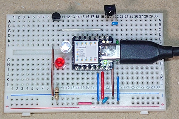
トランジスタっぽく見えているのは, 机上にあったN channel MOSFETね。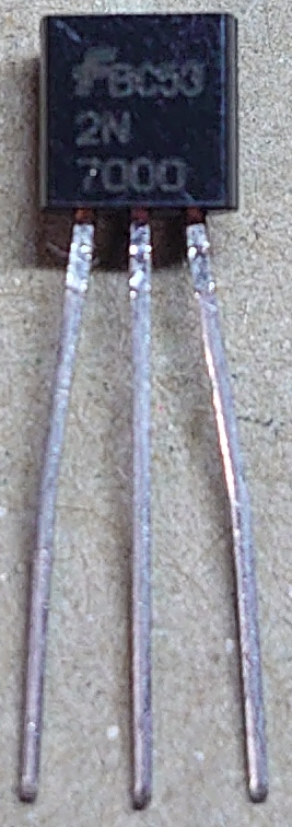
赤外線LEDと赤色LEDを直列につないで, 点滅を目で見れるようにしておくとデバッグに便利ですよ。
LED駆動回路の決め方は #赤外線リモコン のタグをクリックすればそんな内容のページがあるかもね。
コメント