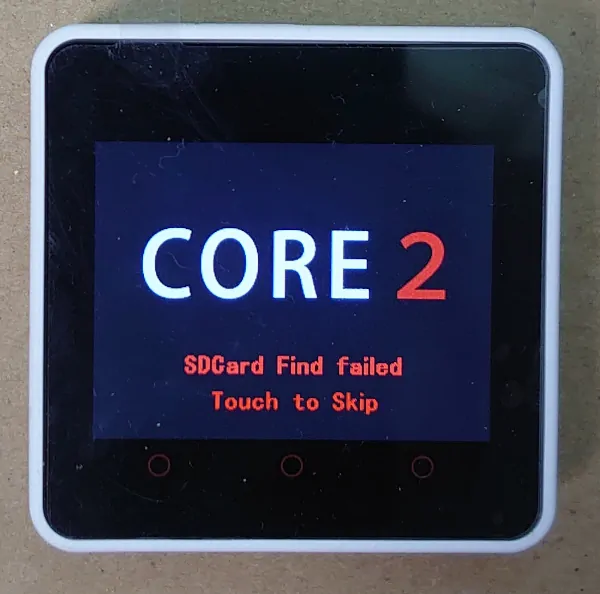
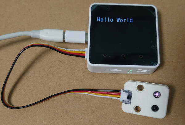
何に使うかは決めていないけれどM5Stack Core2 IoT開発キットを買ってみた。
スイッチをいれるとすでにアプリが入っていた。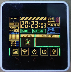
Hello World
新しいマイコンを手に入れたらまずはLEDチカチカかHello World。
VSCode + PlatformIOで開発環境を用意1してM5Stack Core2のディスプレイにHello Worldを表示してみるとする。
#include <M5Core2.h>

#define LGFX_M5STACK_CORE2
#include <LovyanGFX.hpp>

static LGFX lcd;

void setup()
{
  M5.begin(true, true, true, true);
  lcd.init();
  lcd.setFont(&fonts::lgfxJapanGothic_40);
  lcd.println("Hello World");
}

void loop() {}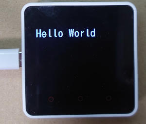
赤外線リモコン信号を送受信してみる
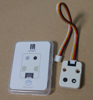
PORT番号は回路図によると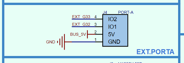
赤外線送受信ユニットの方は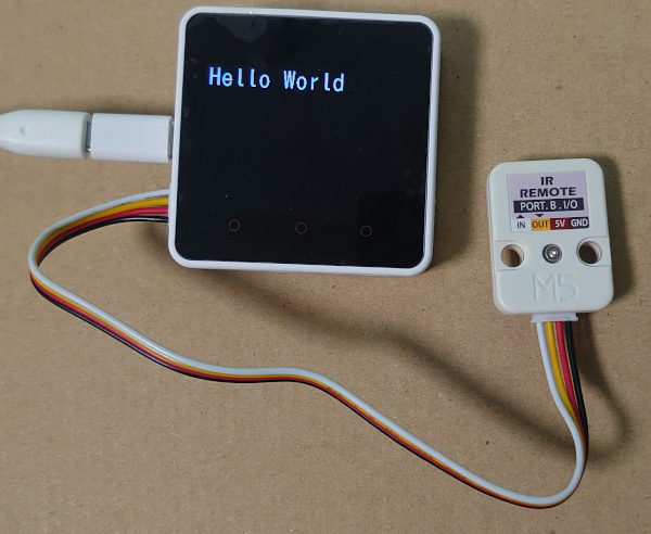
| ピン番号 | M5Stack Core2 | M5Stack用赤外線送受信ユニット |
|---|---|---|
| 1 | GND | GND |
| 2 | 5V | 5V |
| 3 | GPIO32 | OUT(赤外線送信) |
| 4 | GPIO33 | IN(赤外線受信) |
こうだね。
IRremoteESP8266による受信
IRremoteESP8266 という素敵なライブラリがあるので有難く使わしてもらいます。
; PlatformIO Project Configuration File
;
;   Build options: build flags, source filter
;   Upload options: custom upload port, speed and extra flags
;   Library options: dependencies, extra library storages
;   Advanced options: extra scripting
;
; Please visit documentation for the other options and examples
; https://docs.platformio.org/page/projectconf.html

[env:m5stack-core2]
platform = espressif32
board = m5stack-fire
framework = arduino
monitor_speed = 115200
lib_deps =
  https://github.com/m5stack/M5Core2.git
  lovyan03/LovyanGFX
  crankyoldgit/IRremoteESP8266
赤外線リモコン信号受信サンプルソース(IRrecvDumpV3)を
M5 Core2で動くようにカスタマイズして
/*
 * Copyright 2020 Akihiro Yamamoto.
 */
/*
 * IRremoteESP8266: IRrecvDumpV3 - dump details of IR codes with IRrecv
 * An IR detector/demodulator must be connected to the input kRecvPin.
 *
 * Copyright 2009 Ken Shirriff, http://arcfn.com
 * Copyright 2017-2019 David Conran
 *
 * Example circuit diagram:
 *  https://github.com/crankyoldgit/IRremoteESP8266/wiki#ir-receiving
 *
 * Changes:
 *   Version 1.2 October, 2020
 *     - Enable easy setting of the decoding tolerance value.
 *   Version 1.1 May, 2020
 *     - Create DumpV3 from DumpV2
 *     - Add OTA Base
 *   Version 1.0 October, 2019
 *     - Internationalisation (i18n) support.
 *     - Stop displaying the legacy raw timing info.
 *   Version 0.5 June, 2019
 *     - Move A/C description to IRac.cpp.
 *   Version 0.4 July, 2018
 *     - Minor improvements and more A/C unit support.
 *   Version 0.3 November, 2017
 *     - Support for A/C decoding for some protocols.
 *   Version 0.2 April, 2018
 *     - Decode from a copy of the data so we can start capturing faster thus
 *       reduce the likelihood of miscaptures.
 * Based on Ken Shirriff's IrsendDemo Version 0.1 July, 2009,
 */

#include <M5Core2.h>
#include <assert.h>
#include <IRrecv.h>
#include <IRremoteESP8266.h>
#include <IRac.h>
#include <IRtext.h>
#include <IRutils.h>

#define LGFX_M5STACK_CORE2
#include <LovyanGFX.hpp>
static LGFX lcd;

// ==================== start of TUNEABLE PARAMETERS ====================
// An IR detector/demodulator is connected to GPIO pin 14
// e.g. D5 on a NodeMCU board.
// Note: GPIO 16 won't work on the ESP8266 as it does not have interrupts.
const uint16_t kRecvPin = 33;

// The Serial connection baud rate.
// i.e. Status message will be sent to the PC at this baud rate.
// Try to avoid slow speeds like 9600, as you will miss messages and
// cause other problems. 115200 (or faster) is recommended.
// NOTE: Make sure you set your Serial Monitor to the same speed.
const uint32_t kBaudRate = 115200;

// As this program is a special purpose capture/decoder, let us use a larger
// than normal buffer so we can handle Air Conditioner remote codes.
const uint16_t kCaptureBufferSize = 1024;

// kTimeout is the Nr. of milli-Seconds of no-more-data before we consider a
// message ended.
// This parameter is an interesting trade-off. The longer the timeout, the more
// complex a message it can capture. e.g. Some device protocols will send
// multiple message packets in quick succession, like Air Conditioner remotes.
// Air Coniditioner protocols often have a considerable gap (20-40+ms) between
// packets.
// The downside of a large timeout value is a lot of less complex protocols
// send multiple messages when the remote's button is held down. The gap between
// them is often also around 20+ms. This can result in the raw data be 2-3+
// times larger than needed as it has captured 2-3+ messages in a single
// capture. Setting a low timeout value can resolve this.
// So, choosing the best kTimeout value for your use particular case is
// quite nuanced. Good luck and happy hunting.
// NOTE: Don't exceed kMaxTimeoutMs. Typically 130ms.
#if DECODE_AC
// Some A/C units have gaps in their protocols of ~40ms. e.g. Kelvinator
// A value this large may swallow repeats of some protocols
const uint8_t kTimeout = 50;
#else  // DECODE_AC
// Suits most messages, while not swallowing many repeats.
const uint8_t kTimeout = 15;
#endif // DECODE_AC
// Alternatives:
// const uint8_t kTimeout = 90;
// Suits messages with big gaps like XMP-1 & some aircon units, but can
// accidentally swallow repeated messages in the rawData[] output.
//
// const uint8_t kTimeout = kMaxTimeoutMs;
// This will set it to our currently allowed maximum.
// Values this high are problematic because it is roughly the typical boundary
// where most messages repeat.
// e.g. It will stop decoding a message and start sending it to serial at
//      precisely the time when the next message is likely to be transmitted,
//      and may miss it.

// Set the smallest sized "UNKNOWN" message packets we actually care about.
// This value helps reduce the false-positive detection rate of IR background
// noise as real messages. The chances of background IR noise getting detected
// as a message increases with the length of the kTimeout value. (See above)
// The downside of setting this message too large is you can miss some valid
// short messages for protocols that this library doesn't yet decode.
//
// Set higher if you get lots of random short UNKNOWN messages when nothing
// should be sending a message.
// Set lower if you are sure your setup is working, but it doesn't see messages
// from your device. (e.g. Other IR remotes work.)
// NOTE: Set this value very high to effectively turn off UNKNOWN detection.
const uint16_t kMinUnknownSize = 12;

// How much percentage lee way do we give to incoming signals in order to match
// it?
// e.g. +/- 25% (default) to an expected value of 500 would mean matching a
//      value between 375 & 625 inclusive.
// Note: Default is 25(%). Going to a value >= 50(%) will cause some protocols
//       to no longer match correctly. In normal situations you probably do not
//       need to adjust this value. Typically that's when the library detects
//       your remote's message some of the time, but not all of the time.
const uint8_t kTolerancePercentage = kTolerance; // kTolerance is normally 25%

// Legacy (No longer supported!)
//
// Change to `true` if you miss/need the old "Raw Timing[]" display.
#define LEGACY_TIMING_INFO false
// ==================== end of TUNEABLE PARAMETERS ====================

// Use turn on the save buffer feature for more complete capture coverage.
IRrecv irrecv(kRecvPin, kCaptureBufferSize, kTimeout, true);
decode_results results; // Somewhere to store the results

// This section of code runs only once at start-up.
void setup()
{
  M5.begin(true, true, true, false);
  lcd.init();
  lcd.setFont(&fonts::lgfxJapanGothic_40);
  lcd.println("Hello World");

#if defined(ESP8266)
  Serial.begin(kBaudRate, SERIAL_8N1, SERIAL_TX_ONLY);
#else             // ESP8266
  Serial.begin(kBaudRate, SERIAL_8N1);
#endif            // ESP8266
  while (!Serial) // Wait for the serial connection to be establised.
    delay(50);
  // Perform a low level sanity checks that the compiler performs bit field
  // packing as we expect and Endianness is as we expect.
  assert(irutils::lowLevelSanityCheck() == 0);

  Serial.printf("\n" D_STR_IRRECVDUMP_STARTUP "\n", kRecvPin);
#if DECODE_HASH
  // Ignore messages with less than minimum on or off pulses.
  irrecv.setUnknownThreshold(kMinUnknownSize);
#endif                                       // DECODE_HASH
  irrecv.setTolerance(kTolerancePercentage); // Override the default tolerance.
  irrecv.enableIRIn();                       // Start the receiver
}

// The repeating section of the code
void loop()
{
  // Check if the IR code has been received.
  if (irrecv.decode(&results))
  {
    // Display a crude timestamp.
    uint32_t now = millis();
    Serial.printf(D_STR_TIMESTAMP " : %06u.%03u\n", now / 1000, now % 1000);
    // Check if we got an IR message that was to big for our capture buffer.
    if (results.overflow)
      Serial.printf(D_WARN_BUFFERFULL "\n", kCaptureBufferSize);
    // Display the library version the message was captured with.
    Serial.println(D_STR_LIBRARY "   : v" _IRREMOTEESP8266_VERSION_ "\n");
    // Display the tolerance percentage if it has been change from the default.
    if (kTolerancePercentage != kTolerance)
      Serial.printf(D_STR_TOLERANCE " : %d%%\n", kTolerancePercentage);
    // Display the basic output of what we found.
    Serial.print(resultToHumanReadableBasic(&results));
    // Display any extra A/C info if we have it.
    String description = IRAcUtils::resultAcToString(&results);
    if (description.length())
      Serial.println(D_STR_MESGDESC ": " + description);
    yield(); // Feed the WDT as the text output can take a while to print.
#if LEGACY_TIMING_INFO
    // Output legacy RAW timing info of the result.
    Serial.println(resultToTimingInfo(&results));
    yield(); // Feed the WDT (again)
#endif       // LEGACY_TIMING_INFO
    // Output the results as source code
    Serial.println(resultToSourceCode(&results));
    Serial.println(); // Blank line between entries
    yield();          // Feed the WDT (again)
  }
}Panasonic製エアコンリモコンで送信した「暖房23℃」の信号を読ませてみると。
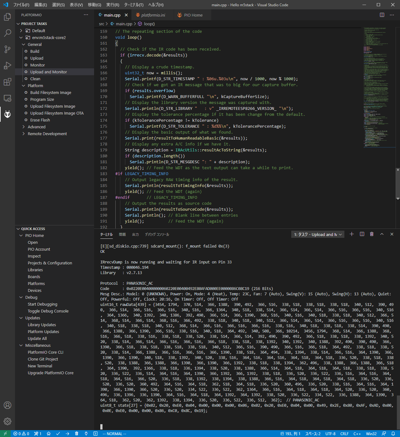
これはシリアルコンソールに出力された内容
IRrecvDump is now running and waiting for IR input on Pin 33
Timestamp : 000046.194
Library   : v2.7.13

Protocol  : PANASONIC_AC
Code      : 0x0220E004000000060220E00400492E80AFAD000EE0000086C08C19 (216 Bits)
Mesg Desc.: Model: 0 (UNKNOWN), Power: On, Mode: 4 (Heat), Temp: 23C, Fan: 7 (Auto), Swing(V): 15 (Auto), Swing(H): 13 (Auto), Quiet:
Off, Powerful: Off, Clock: 20:16, On Timer: Off, Off Timer: Off
uint16_t rawData[439] = {3454, 1794,  370, 514,  366, 1388,  390, 492,  366, 516,  338, 518,  338, 518,  338, 518,  340, 512,  390, 490,  366, 514,  366, 516,  366, 516,  340, 516,  366, 1364,  340, 518,  338, 514,  366, 514,  366, 514,  366, 516,  366, 516,  340, 516,  364, 1366,  340, 1392,  340, 1386,  392, 490,  366, 514,  366, 1390,  368, 516,  340, 516,  340, 518,  338, 518,  340, 512,  366, 514,  368, 514,  366, 514,  368, 516,  366, 492,  338, 518,  340, 518,  340, 512,  366, 514,  366, 514,  366, 516,  366, 516,  340, 516,  340, 518,  338, 518,  340, 512,  368, 514,  366, 516,  366, 516,  366, 516,  338, 516,  340, 518,  338, 518,  338, 514,  390, 490,
 366, 1388,  366, 1390,  366, 516,  338, 516,  340, 518,  364, 492,  340, 508,  366, 10214,  3456, 1794,  368, 514,  366, 1388,  368,
516,  366, 518,  338, 516,  338, 518,  338, 520,  338, 514,  366, 514,  392, 490,  390, 492,  366, 518,  338, 518,  338, 1392,  340, 520,  338, 514,  366, 514,  366, 516,  366, 516,  366, 518,  338, 518,  338, 1392,  340, 1392,  340, 1388,  392, 490,  390, 490,  366,
1390,  366, 518,  338, 518,  338, 518,  338, 518,  340, 512,  366, 516,  390, 490,  366, 516,  366, 518,  364, 492,  338, 518,  338, 520,  338, 514,  366, 1388,  366, 516,  366, 516,  366, 1390,  338, 518,  364, 494,  338, 1394,  338, 514,  366, 516,  364, 1390,  366, 1390,  366, 1390,  340, 518,  338, 1392,  340, 520,  338, 516,  364, 516,  364, 516,  364, 518,  364, 518,  336, 520,  338, 518,  338, 520,  338, 1388,  366, 1388,  366, 1390,  366, 1390,  366, 1392,  338, 518,  338, 1394,  362, 496,  338, 1388,  366, 1388,  366, 518,  364, 1390,  392, 1366,  338, 518,  336, 1394,  338, 520,  338, 1388,  366, 514,  364, 518,  364, 518,  364, 518,  338, 518,  338, 520,  336, 522,  336, 514,  364, 516,  364, 1390,  366, 1392,  366, 1392,  338, 518,  336, 520,  336, 522,  336, 516,  364, 516,  364,
518,  364, 516,  366, 520,  336, 518,  338, 1392,  338, 1394,  338, 1388,  366, 516,  364, 518,  364, 518,  364, 518,  336, 520,  336, 520,  336, 520,  360, 492,  364, 516,  364, 518,  362, 518,  364, 518,  336, 520,  360, 496,  336, 520,  338, 516,  364, 516,  364, 1390,  366, 1390,  366, 520,  336, 520,  334, 522,  336, 522,  362, 1364,  366, 516,  364, 518,  364, 518,  364, 520,  336, 520,  360,
496,  336, 1396,  336, 1390,  364, 516,  364, 518,  364, 1392,  364, 1392,  338, 520,  336, 522,  334, 522,  336, 1388,  364, 1390,  364, 518,  362, 520,  362, 1392,  338, 1394,  336, 520,  336, 522,  336, 512,  362};  // PANASONIC_AC
uint8_t state[27] = {0x02, 0x20, 0xE0, 0x04, 0x00, 0x00, 0x00, 0x06, 0x02, 0x20, 0xE0, 0x04, 0x00, 0x49, 0x2E, 0x80, 0xAF, 0xAD, 0x00, 0x0E, 0xE0, 0x00, 0x00, 0x86, 0xC0, 0x8C, 0x19};- Protocol: PANASONIC_AC
- Model: 0 (UNKNOWN)
- Power: On
- Mode: 4 (Heat)
- Temp: 23C
- Fan: 7 (Auto)
- Swing(V): 15 (Auto)
- Swing(H): 13 (Auto)
- Quiet: Off
- Powerful: Off
- Clock: 20:16
- On Timer: Off
- Off Timer: Off
ちゃんとあってる。すごいねー。
IRremoteESP8266による送信
受信が問題なくできたので続いて送信をしてみる。
赤外線リモコン信号送信サンプルソース(CommonAcControl)を
カスタマイズして
/*
 * Copyright 2020 Akihiro Yamamoto
 */
/* Copyright 2019 David Conran
*
* This example code demonstrates how to use the "Common" IRac class to control
* various air conditions. The IRac class does not support all the features
* for every protocol. Some have more detailed support that what the "Common"
* interface offers, and some only have a limited subset of the "Common" options.
*
* This example code will:
* o Try to turn on, then off every fully supported A/C protocol we know of.
* o It will try to put the A/C unit into Cooling mode at 25C, with a medium
*   fan speed, and no fan swinging.
* Note: Some protocols support multiple models, only the first model is tried.
*
*/
#include <M5Core2.h>
#include <IRremoteESP8266.h>
#include <IRac.h>
#include <IRutils.h>

#define LGFX_M5STACK_CORE2
#include <LovyanGFX.hpp>
static LGFX lcd;

const unsigned long background_color = 0x000000U;
const unsigned long message_text_color = 0xFF0000U;

const uint16_t kIrLed = 32; // The ESP GPIO pin to use that controls the IR LED.
IRac ac(kIrLed);            // Create a A/C object using GPIO to sending messages with.

void send_panasonic_ac()
{
  // Set up what we want to send.
  // See state_t, opmode_t, fanspeed_t, swingv_t, & swingh_t in IRsend.h for
  // all the various options.
  ac.next.protocol = decode_type_t::DAIKIN;      // Set a protocol to use.
  ac.next.model = 1;                             // Some A/Cs have different models. Try just the first.
  ac.next.mode = stdAc::opmode_t::kCool;         // Run in cool mode initially.
  ac.next.celsius = true;                        // Use Celsius for temp units. False = Fahrenheit
  ac.next.degrees = 25;                          // 25 degrees.
  ac.next.fanspeed = stdAc::fanspeed_t::kMedium; // Start the fan at medium.
  ac.next.swingv = stdAc::swingv_t::kOff;        // Don't swing the fan up or down.
  ac.next.swingh = stdAc::swingh_t::kOff;        // Don't swing the fan left or right.
  ac.next.light = false;                         // Turn off any LED/Lights/Display that we can.
  ac.next.beep = false;                          // Turn off any beep from the A/C if we can.
  ac.next.econo = false;                         // Turn off any economy modes if we can.
  ac.next.filter = false;                        // Turn off any Ion/Mold/Health filters if we can.
  ac.next.turbo = false;                         // Don't use any turbo/powerful/etc modes.
  ac.next.quiet = false;                         // Don't use any quiet/silent/etc modes.
  ac.next.sleep = -1;                            // Don't set any sleep time or modes.
  ac.next.clean = false;                         // Turn off any Cleaning options if we can.
  ac.next.clock = -1;                            // Don't set any current time if we can avoid it.
  ac.next.power = false;                         // Initially start with the unit off.

  // customized
  auto protocol = decode_type_t::PANASONIC_AC;
  ac.next.protocol = protocol;
  ac.next.model = 0;
  ac.next.mode = stdAc::opmode_t::kHeat;
  ac.next.celsius = true;
  ac.next.degrees = 23;
  ac.next.fanspeed = stdAc::fanspeed_t::kMax;
  ac.next.power = true;

  if (ac.isProtocolSupported(protocol))
  {
    Serial.println("Protocol " + String(protocol) + " / " +
                   typeToString(protocol) + " is supported.");

    ac.sendAc();
    Serial.println("Send IR");
  }
}

void releaseEvent(Event &e)
{
  lcd.setFont(&fonts::lgfxJapanGothic_40);
  lcd.setTextColor(message_text_color, background_color);
  lcd.setTextDatum(textdatum_t::middle_center);
  lcd.drawString("SEND", lcd.width() / 2, lcd.height() / 2);
  send_panasonic_ac();
  delay(1000); // Wait 1 second.
  lcd.setTextColor(background_color, background_color);
  lcd.drawString("SEND", lcd.width() / 2, lcd.height() / 2);
}

void setup()
{
  M5.begin(true, true, true, false);

  M5.Buttons.addHandler(releaseEvent, E_RELEASE);

  lcd.init();
  lcd.setFont(&fonts::lgfxJapanGothic_28);
  lcd.println("TOUCH TO SEND IR");

  Serial.begin(115200);
  delay(200);
}

void loop()
{
  M5.update();
}ビルドして書き込むとこう表示されるから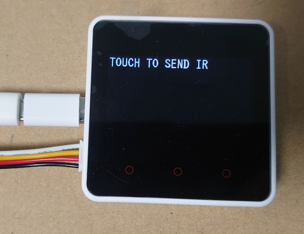
画面のどこでも押すと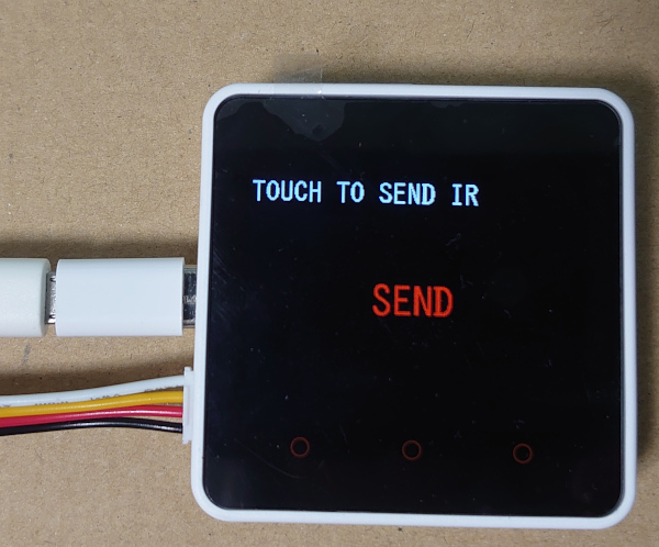
赤外線信号が送信されて(すでに動いている)エアコンのファンが最大風量になった。
赤外線リモコンがこんなに簡単にできた。すごいね。
ほんとマイコンのプログラミングも便利になったね。
今時はんだ付けとか必要ないねんな。
7セグメントディスプレイを使ってみる
製品を買ってつないだだけで終わるのもなんか味気ないので, LEDチカチカの代わりに7セグメントディスプレイに数字を表示してみる。
今回は M5Stack Core2のI2CバスにPCF8574を使って7セグメントディスプレイをつなぐ。
使った7セグメントディスプレイのデーターシートはこれです。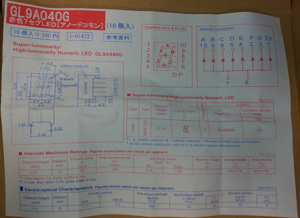
PCF8574のデーターシートからピン配列とI2Cアドレス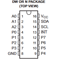
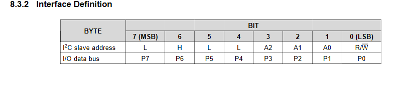
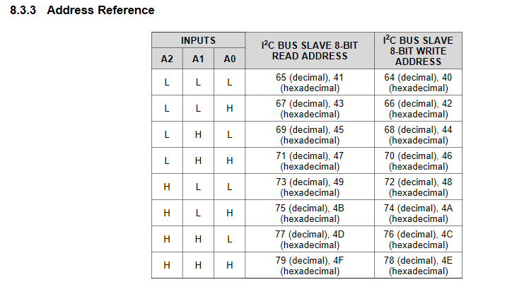
今回は(アドレス選択)A0,A1,A2共にGNDに接続したので
0100000x = 0x20(I2Cアドレス)
01000000 = 0x40(write address)
01000001 = 0x41(read address)
になる(ソースコードで指定するのはI2Cアドレス)。
/*
 * Copyright 2020 Akihiro Yamamoto
 */
#include <M5Core2.h>
#include <memory>

#define LGFX_M5STACK_CORE2
#include <LovyanGFX.hpp>
static LGFX lcd;

const unsigned short i2c_address_7seg = 0x20;

// 7SEG display
//
//   A
// F   B
//   G
// E   C
//   D   (D.P.)
//
// PCF8574 -> 7SEG
// P0 -> F
// P1 -> G
// P2 -> E
// P3 -> D
// P4 -> A
// P5 -> B
// P6 -> C
// P7 -> D.P.
//
const uint8_t table_7seg[10] = {
    //(D.P.)CBADEGF 負論理
    0b10000010, // 0 --> C, B, A, D, E, _ ,F
    0b10011111, // 1 --> C, B, _, _, _, _ ,_
    0b11000001, // 2 --> _, B, A, D, E, G ,_
    0b10000101, // 3 --> C, B, A, D, _, G ,_
    0b10011100, // 4 --> C, B, _, _, _, G ,F
    0b10100100, // 5 --> C, _, A, D, _, G ,F
    0b10100000, // 6 --> C, _, A, D, E, G ,F
    0b10001110, // 7 --> C, B, A, _, _, _ ,F
    0b10000000, // 8 --> C, B, A, D, E, G ,F
    0b10000100, // 9 --> C, B, A, D, _, G ,F
};

const unsigned long background_color = 0x000000U;
const unsigned long message_text_color = 0xFF0000U;

void releaseEvent(Event &e)
{
  static uint8_t display_counter = 0;

  lcd.setFont(&fonts::lgfxJapanGothic_40);
  lcd.setTextColor(message_text_color, background_color);
  lcd.setTextDatum(textdatum_t::middle_center);

  lcd.drawNumber(display_counter, lcd.width() / 2, lcd.height() / 2);

  M5.I2C.writeCommand(i2c_address_7seg, table_7seg[display_counter]);

  delay(500); // Wait 500 millisecond.
  lcd.setTextColor(background_color, background_color);
  lcd.drawNumber(display_counter, lcd.width() / 2, lcd.height() / 2);

  display_counter = (display_counter + 1) % 10;
}

void i2c_scan()
{
  std::unique_ptr<bool[]> result{new bool[128]()};
  M5.I2C.scanID(result.get());
  Serial.printf("Detected I2C device.\n");
  for (unsigned short i = 0; i < 127; i++)
  {
    if (result.get()[i])
    {
      Serial.printf("address: 0x%0x (read: 0x%0x, write: 0x%0x) \n", i, i << 1 | 1, i << 1 | 0);
    }
  }
}

void setup()
{
  M5.begin(true, true, true, true);

  M5.I2C.writeCommand(i2c_address_7seg, table_7seg[0]);

  M5.Buttons.addHandler(releaseEvent, E_RELEASE);

  i2c_scan();

  lcd.init();
  lcd.setFont(&fonts::lgfxJapanGothic_28);
  lcd.println("TOUCH TO SHIFT");

  Serial.begin(115200);
}

void loop()
{
  M5.update();
}ビルドして実行すると。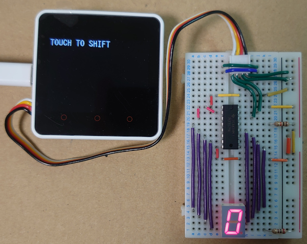
画面を押すと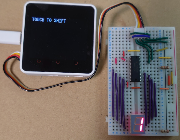
画面を押すたびに0~9までを繰り返す。
回路図を書くのが面倒なので, 接続は写真をよく見てください。
面倒だから7セグディスプレイの共通線側に電流制限抵抗を付けているけどこれはマネしないでね。
正しくは共通線側を電源直結にして7セグディスプレイのピンそれぞれに抵抗を付けるように接続してください。
ほんとマイコンのプログラミングも便利になったね。(2回目)
コメント