前回の続き。
STM32マイコン STM32L010F4P6 で
マイクロサーボ SG92R を動かした。
データシートを確認する
STM32マイコン STM32L010F4P6のデータシートは前回と同じなので省略。
マイクロサーボSG92Rのデータシートそのものが見つからなかったので,
マイクロサーボ9g SG-90 のデータシートを参照する。
 SG-90_ds
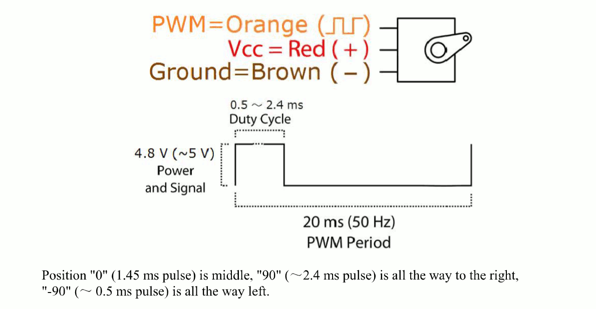
Specifications
- Operating voltage: 3.3V(~6V)
- 20ms(50Hz) PWM Period
- 0.5 ~ 2.4ms Duty Cycle
- 4.8V(~5V) Power and Signal
とのこと。
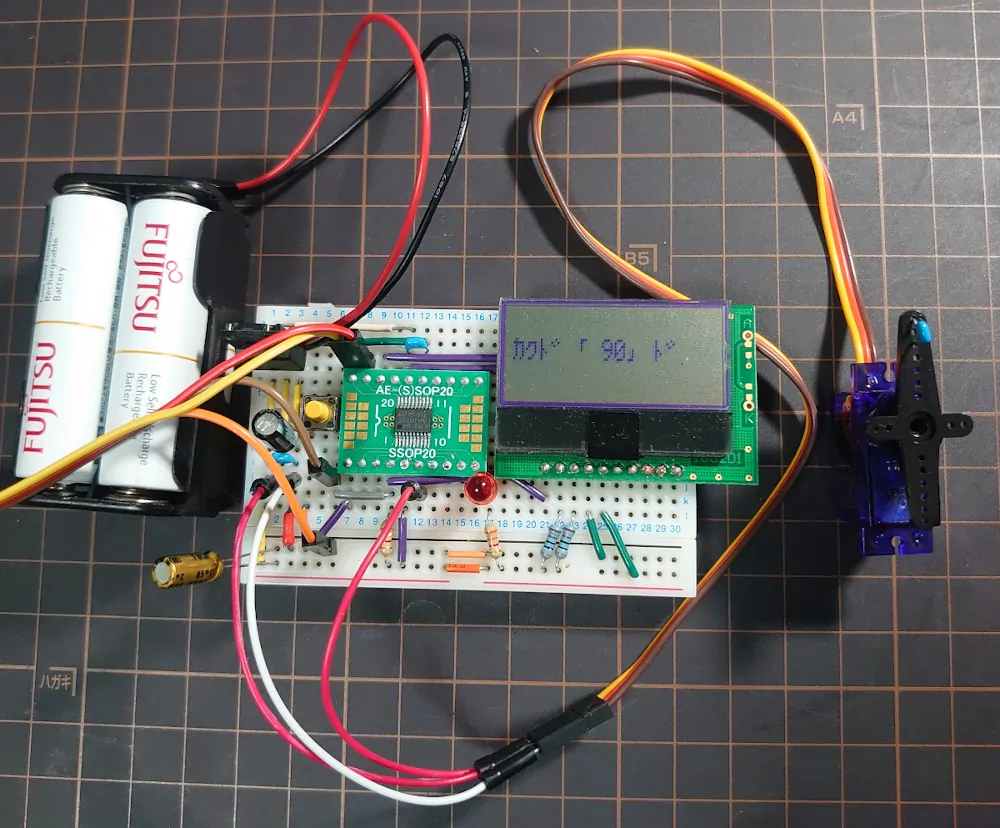
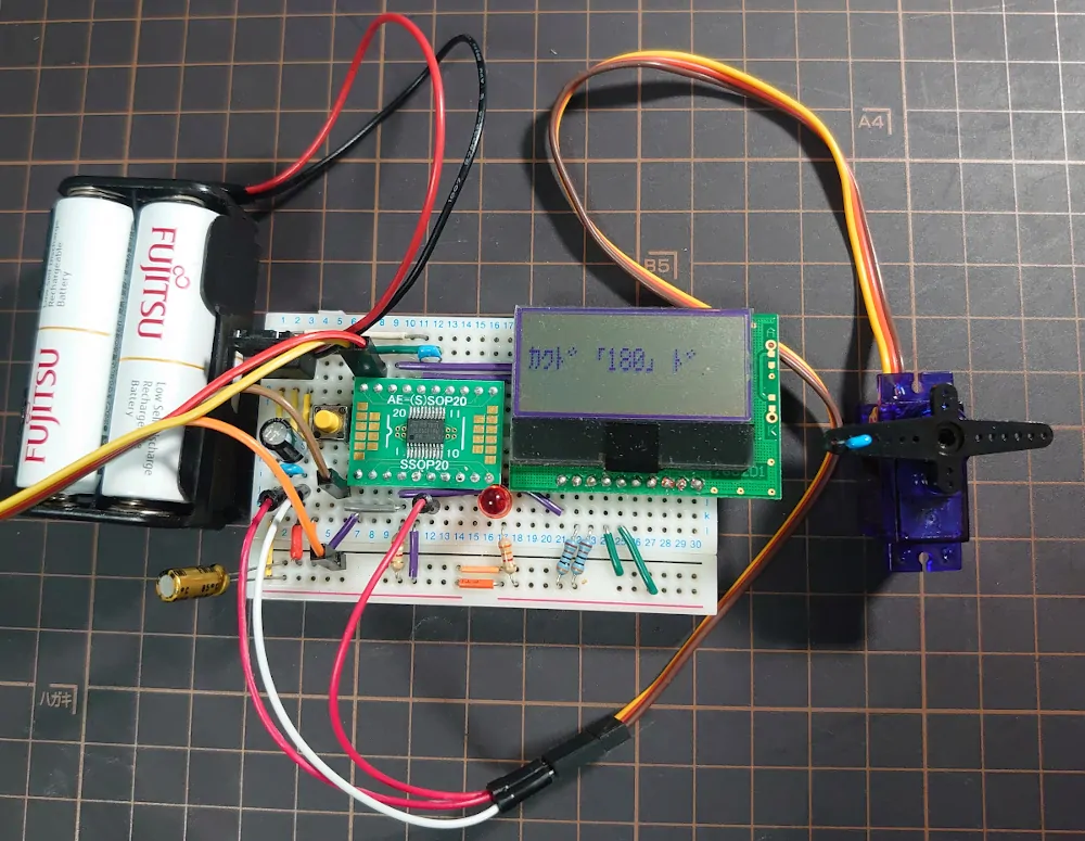
つまりサーボコネクタの赤色線を電源の+に, 茶色線をGNDに接続して橙色線に図に書かれている信号を入力すると動く。
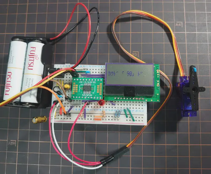
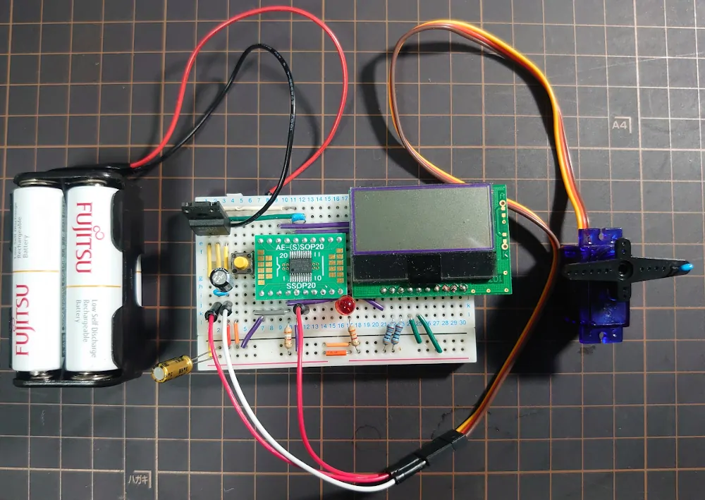
STM32とSG92Rサーボを接続
前回の回路にSG92Rサーボを追加した。
STM32CubeIDEでプロジェクトを開く
前回のプロジェクトを再利用する。
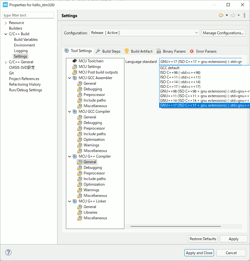
CubeIDEをアップデートしたので Version: 1.8.0。
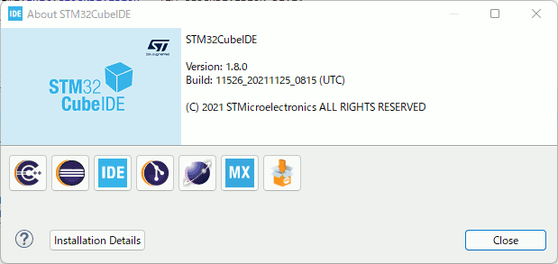
なんとC++17を選択できるようになっていたので選んでみた。
(前から選べたかも知れない。)
STM32L010F4P6のタイマ設定
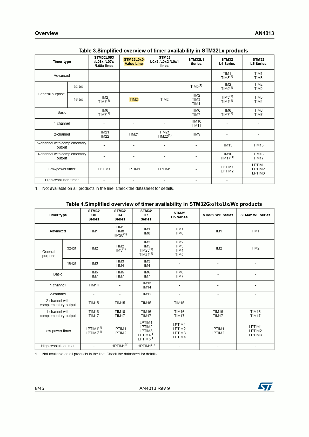
PWM信号はSTM32L010F4P6のGeneral-purpose timerである TIM2 を PWM mode に設定して作ることにする。
タイマ割り込みを使わないのでTIM2 global interruptはデフォルト設定。
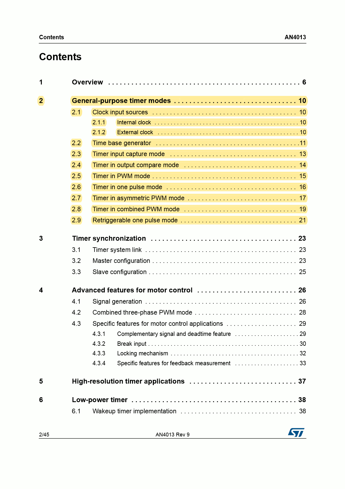
Application note AN4013 - st.com
STM32 cross-series timer overviewより引用。
 an4013_p01
 an4013_p02
 an4013_p08
PA0をTIM2_CH1に割り当ててPWM出力ピンにする。
(このピンにSG92Rの橙色線を接続する。)
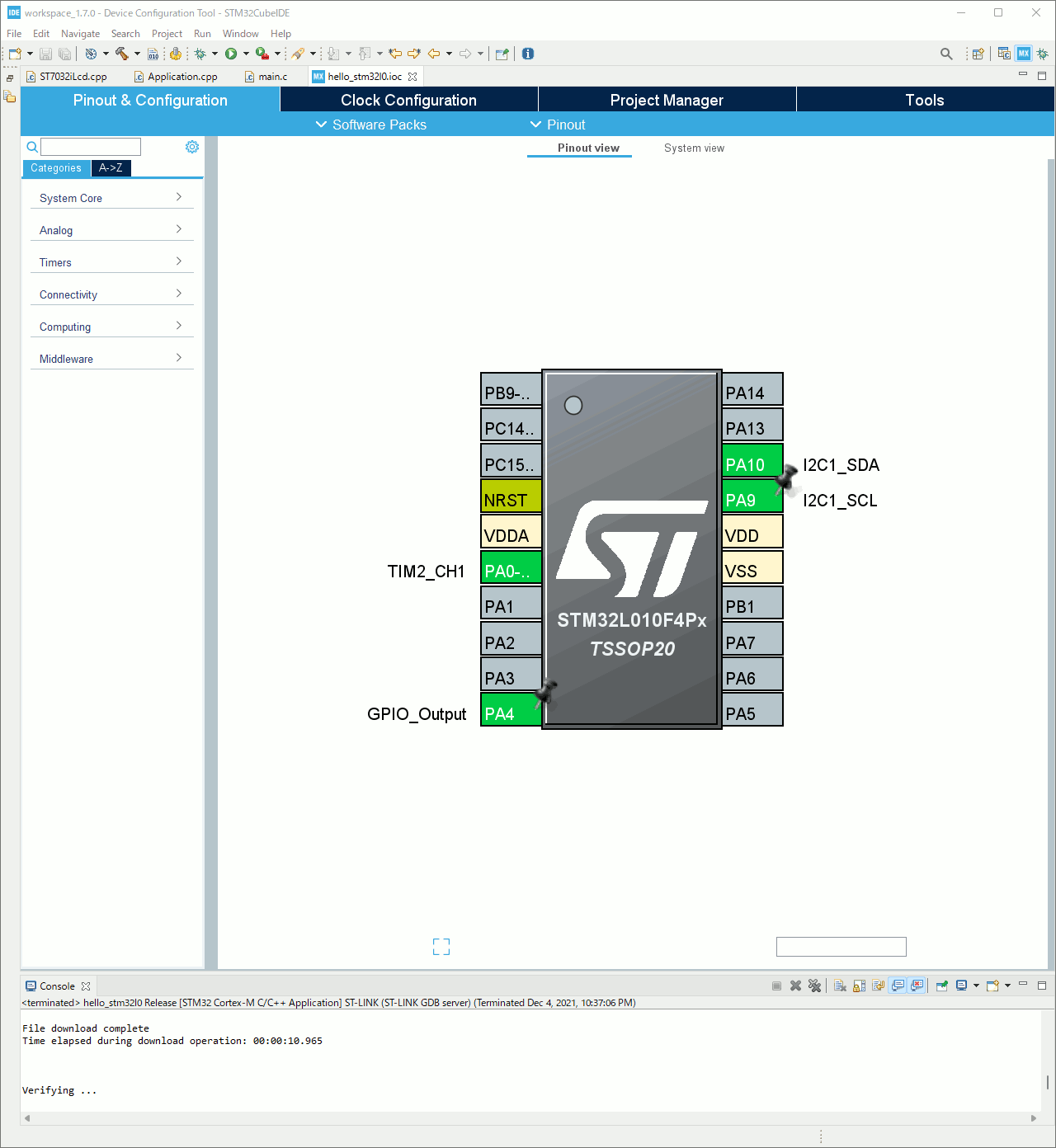
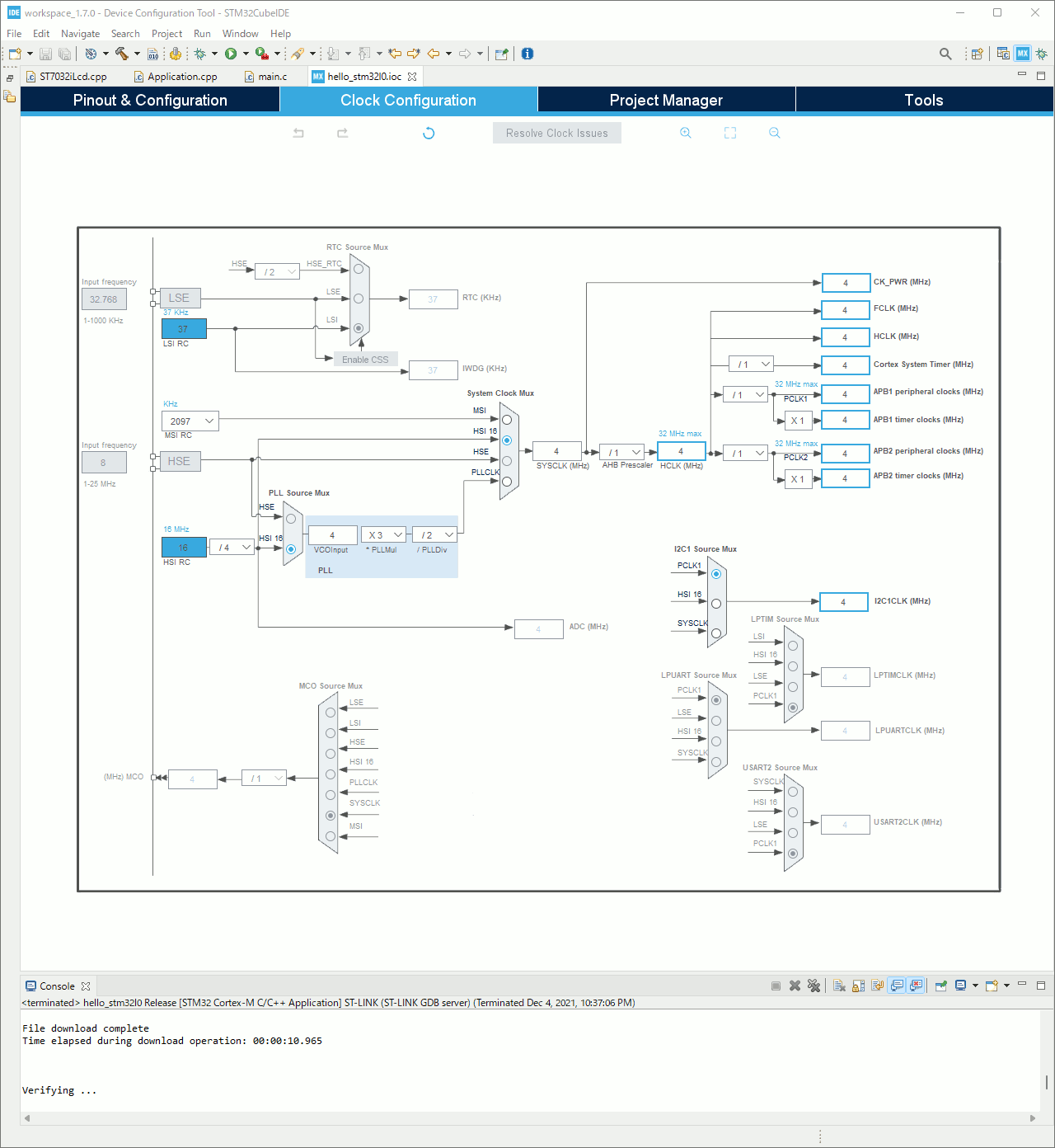
とりあえずクロックは4MHzに設定する。
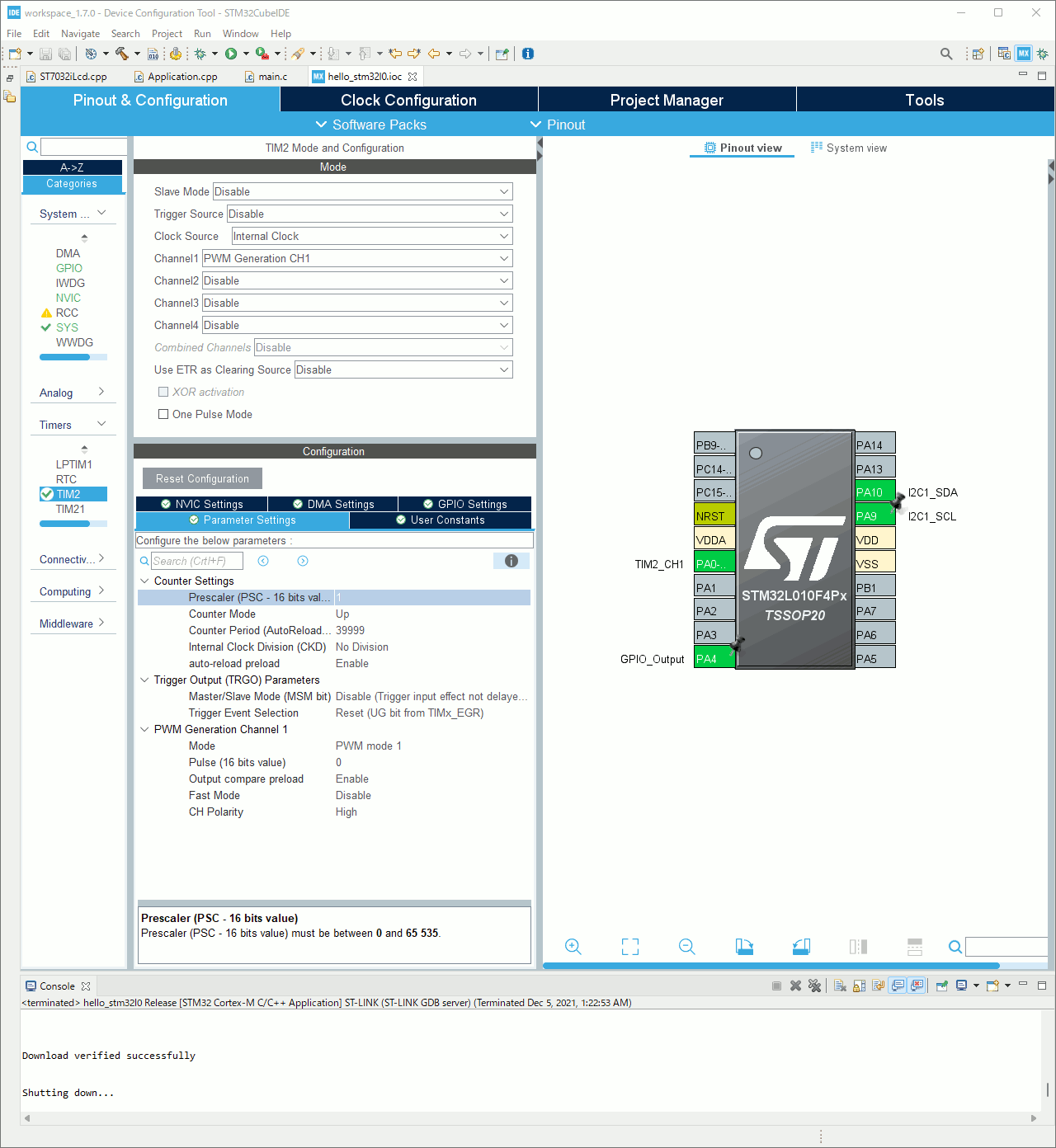
TIM2の設定。
- Clock Source(クロック源): Internal Clock
- Channel1: PWM Generation CH1
- Prescaler(プリスケーラ) : 1
- Counter Period (周期) : 39999
- auto-reload preload: Enable
- Output compare preload: Enable
Prescaler (PSC - 16 bits value)
Prescaler (PSC - 16 bits value) must be between 0 and 65 535.
Counter Period (AutoReload Register - 16 bits value )
Counter Period (AutoReload Register - 16 bits value ) must be between 0 and 65 535.
 screenshot05
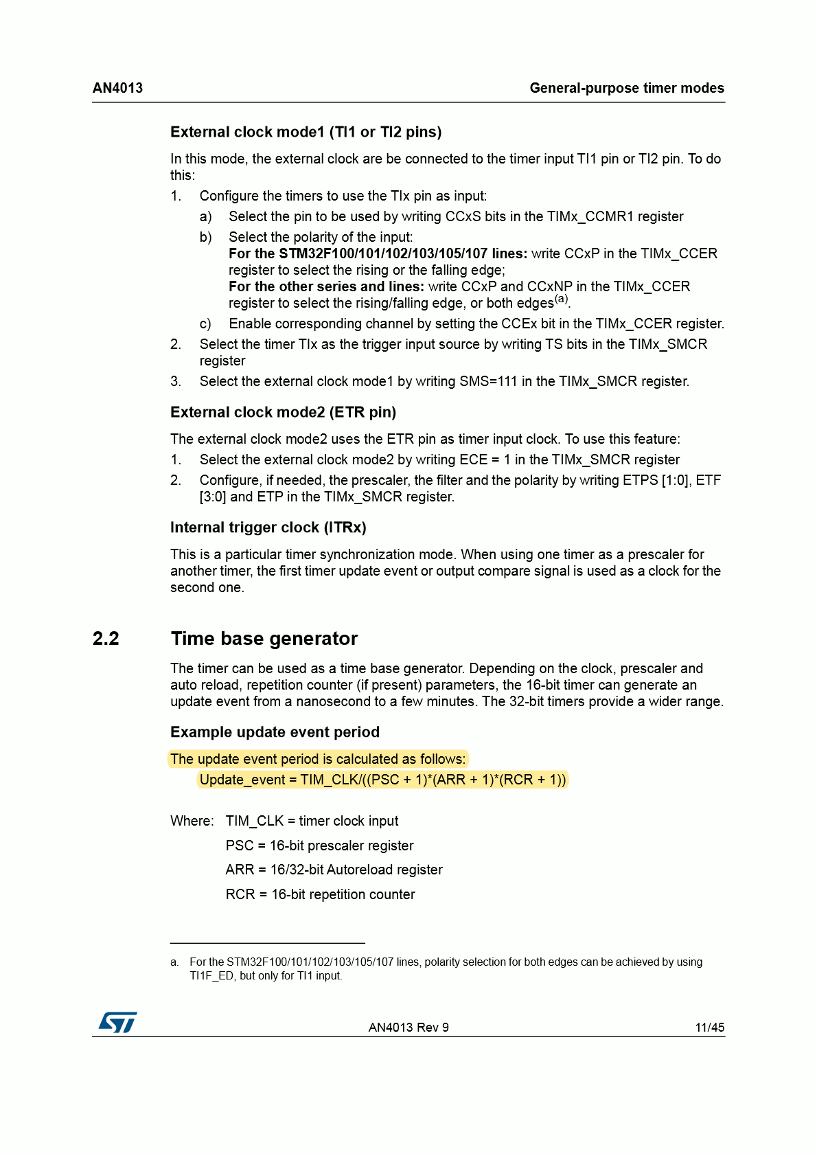
タイマ周期は50Hzになるように, 以下の計算式より算出した。
 an4013
 an4013
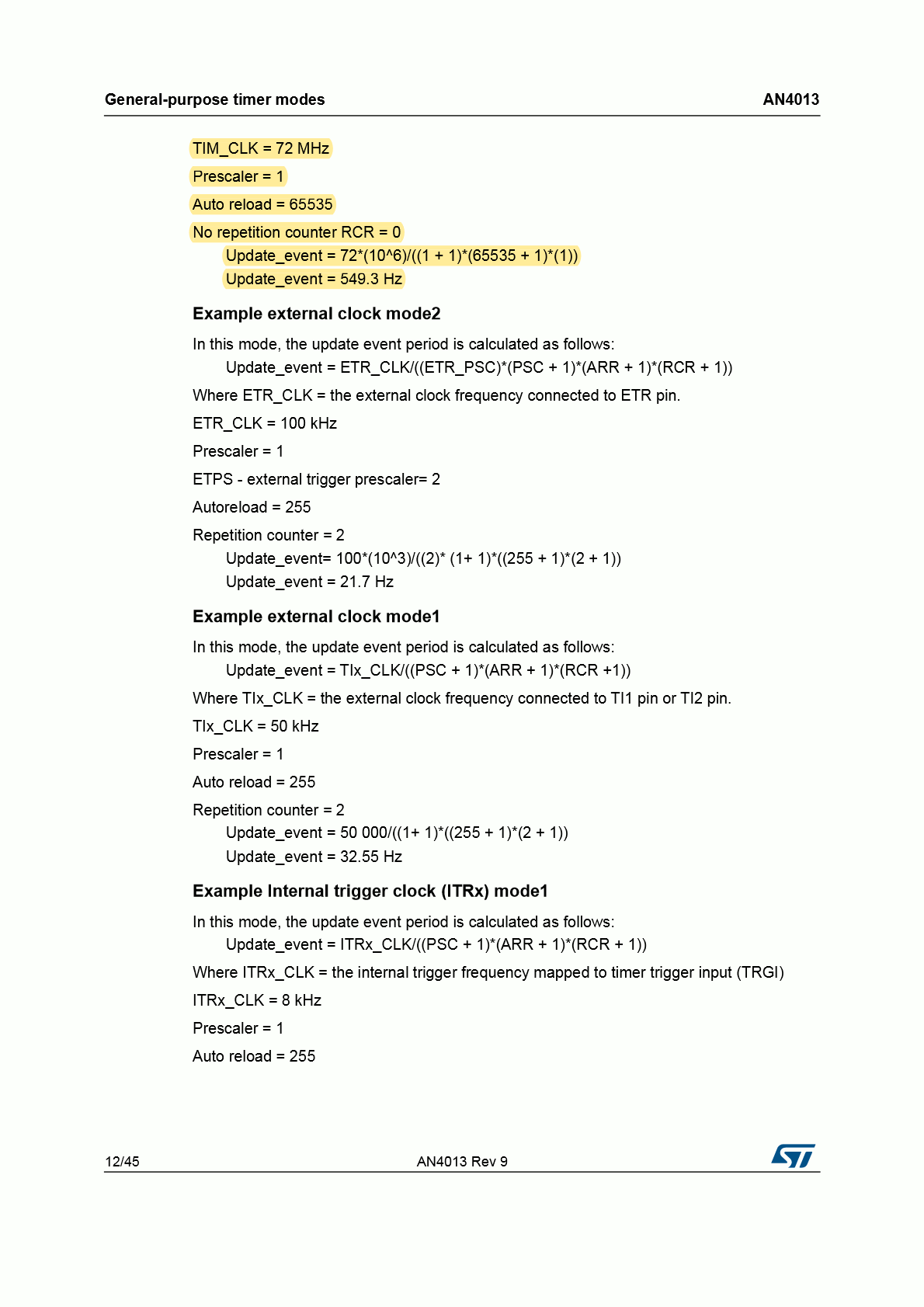
Updateevent=(PSC+1)×(ARR+1)×(RCR+1)TIM_CLK
より
ほしい値は各レジスタの設定値なので
右辺の分母を両辺に掛けて, Update_event を両辺から割ると
(PSC+1)×(ARR+1)×(RCR+1)=Update_eventTIM_CLK
となって
ここに
- TIM_CLK = 4 MHz つまり 4×10⁶ Hz
- Update_event = 50 Hz
- RCR(16-bit repetition counter)は無いので RCR = 0
を代入して
(PSC+1)×(ARR+1)=504×106=504×102×104=50400×104=8×104=80000
STM32L010F4P6マイコンの ARRレジスタは16ビットレジスタなので, そのレジスタに設定できる最大値は 216−1=65535
計算で得られた値 80000 は ARRレジスタの最大値を超える値なので設定できない。
なのでプリスケーラでクロック源から1/2にする設定(PSC=1)にする。
(1+1)×(ARR+1)2×(ARR+1)ARR+1ARR=80000=80000=280000=280000−1=39999
結果
Prescaler (PSC - 16 bits value) には 1を
Counter Period (AutoReload Register - 16 bits value ) には 39999を
設定する。
SG92Rを動かすプログラム
SG92Rを0°から45°づつ180°まで繰り返し動くプログラムを書いてみた。
 1
 2
 3
 4
 5
 6
 7
 8
 9
10
11
12
13
14
15
16
17
18
19
20
21
22
23
24
25
26
27
28
29
30
31
32
33
34
35
36
37
38
39
40
41
42
43
44
45
46
47
48
49
50
| /*
* Application.cpp
*
* Copyright 2021 Akihiro Yamamoto.
* Licensed under the Apache License, Version 2.0
* <https://spdx.org/licenses/Apache-2.0.html>
*
*/
#include <ST7032iLcd.hpp>
extern I2C_HandleTypeDef hi2c1;
extern TIM_HandleTypeDef htim2;
static ST7032iLcd i2c_lcd(hi2c1);
using PwmTimerCounts = uint16_t;
constexpr static const PwmTimerCounts PwmPeriod =
40000; // 40000 counts = 20 milliseconds
constexpr static const PwmTimerCounts ServoAngle0 =
PwmPeriod * 0.5 / 20.0; // 0.5 milliseconds / 20 milliseconds
constexpr static const PwmTimerCounts ServoAngle180 =
PwmPeriod * 2.4 / 20.0; // 2.4 milliseconds / 20 milliseconds
// degree: 0 to 180
static void moveTo(uint8_t degree) {
uint32_t count = ServoAngle0 + (ServoAngle180 - ServoAngle0) * degree / 180;
__HAL_TIM_SET_COMPARE(&htim2, TIM_CHANNEL_1, count);
std::string buff(50, ' ');
std::snprintf(buff.data(), buff.size(), u8"カクド 「%3d」 ド", degree);
i2c_lcd.setDdramAddress(0);
i2c_lcd.putString(buff);
}
extern "C" void application_setup() {
i2c_lcd.init();
moveTo(0);
HAL_TIM_PWM_Start(&htim2, TIM_CHANNEL_1);
}
extern "C" void application_loop() {
constexpr static const uint8_t step_angles = 45;
constexpr static const uint8_t num_of_detents = 1 + 180 / step_angles;
constexpr static const uint8_t slow_down = 30;
static uint16_t i = 0;
HAL_GPIO_TogglePin(GPIOA, GPIO_PIN_4);
HAL_Delay(200);
moveTo(i / slow_down * step_angles);
i = (i + 1) % (slow_down * num_of_detents);
}
|
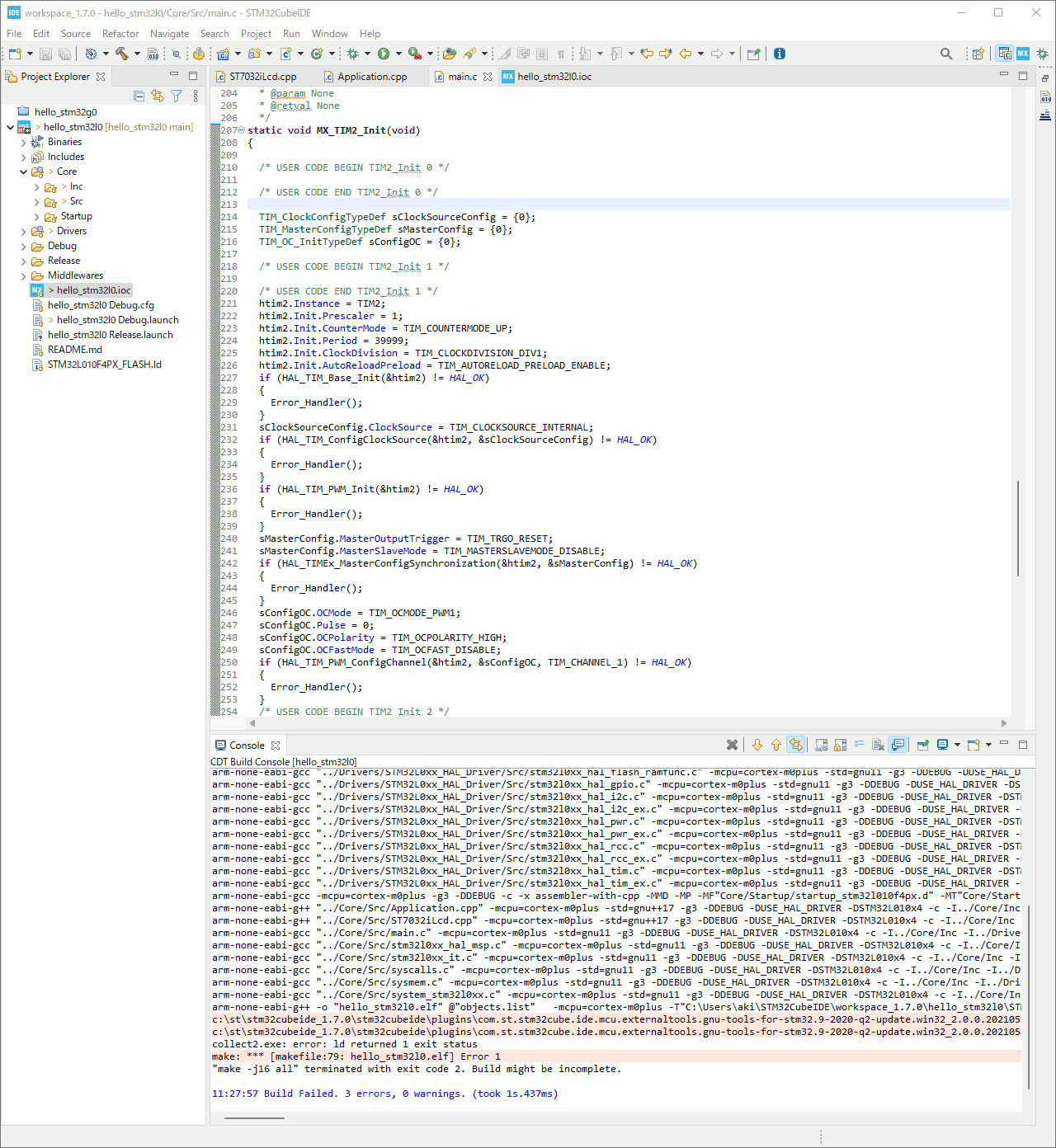
プロジェクトのビルド
Ctrl + B でビルド。
 screenshot06
 1
2
3
4
5
6
7
8
9
10
| 11:30:31 **** Incremental Build of configuration Debug for project hello_stm32l0 ****
make -j16 all
arm-none-eabi-g++ -o "hello_stm32l0.elf" @"objects.list" -mcpu=cortex-m0plus -T"C:\Users\aki\STM32CubeIDE\workspace_1.7.0\hello_stm32l0\STM32L010F4PX_FLASH.ld" --specs=nosys.specs -Wl,-Map="hello_stm32l0.map" -Wl,--gc-sections -static --specs=nano.specs -mfloat-abi=soft -mthumb -Wl,--start-group -lc -lm -lstdc++ -lsupc++ -Wl,--end-group
c:\st\stm32cubeide_1.7.0\stm32cubeide\plugins\com.st.stm32cube.ide.mcu.externaltools.gnu-tools-for-stm32.9-2020-q2-update.win32_2.0.0.202105311346\tools\arm-none-eabi\bin\ld.exe: hello_stm32l0.elf section `.text' will not fit in region `FLASH'
c:\st\stm32cubeide_1.7.0\stm32cubeide\plugins\com.st.stm32cube.ide.mcu.externaltools.gnu-tools-for-stm32.9-2020-q2-update.win32_2.0.0.202105311346\tools\arm-none-eabi\bin\ld.exe: region `FLASH' overflowed by 3892 bytes
collect2.exe: error: ld returned 1 exit status
make: *** [makefile:79: hello_stm32l0.elf] Error 1
"make -j16 all" terminated with exit code 2. Build might be incomplete.
11:30:32 Build Failed. 3 errors, 0 warnings. (took 348ms)
|
はい、エラー。
1
| ld.exe: region `FLASH' overflowed by 3892 bytes
|
FLASH領域から溢れた。
あふれたのは仕方がないのでReleaseビルドにする。
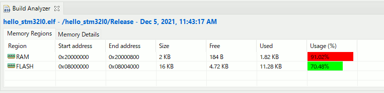
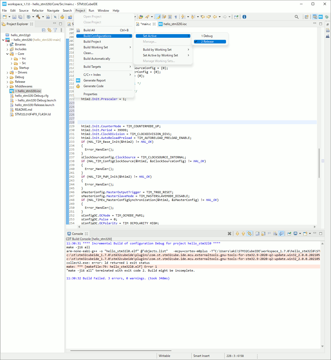 screenshot07
1
2
3
4
5
6
7
8
9
| 11:43:25 **** Incremental Build of configuration Release for project hello_stm32l0 ****
make -j16 all
arm-none-eabi-size hello_stm32l0.elf
text data bss dec hex filename
11424 124 1752 13300 33f4 hello_stm32l0.elf
Finished building: default.size.stdout
11:43:25 Build Finished. 0 errors, 0 warnings. (took 217ms)
|
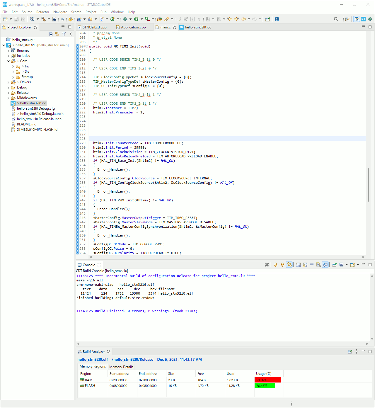 screenshot08
デバッグ関連のコードが無くなるので、収まった。
 screenshot09
ST-Linkでプログラミング
前回と同じなので省略。
実行
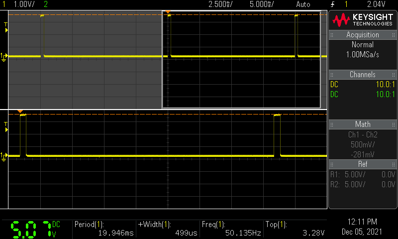
サーボ角度 0 度
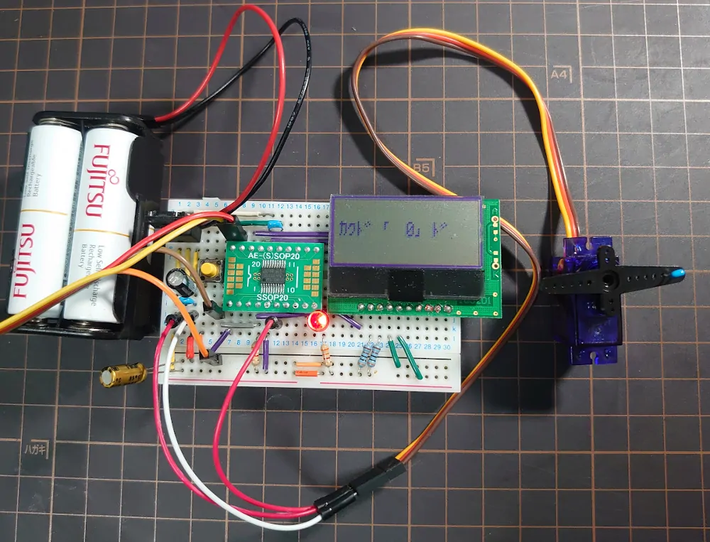 angle0
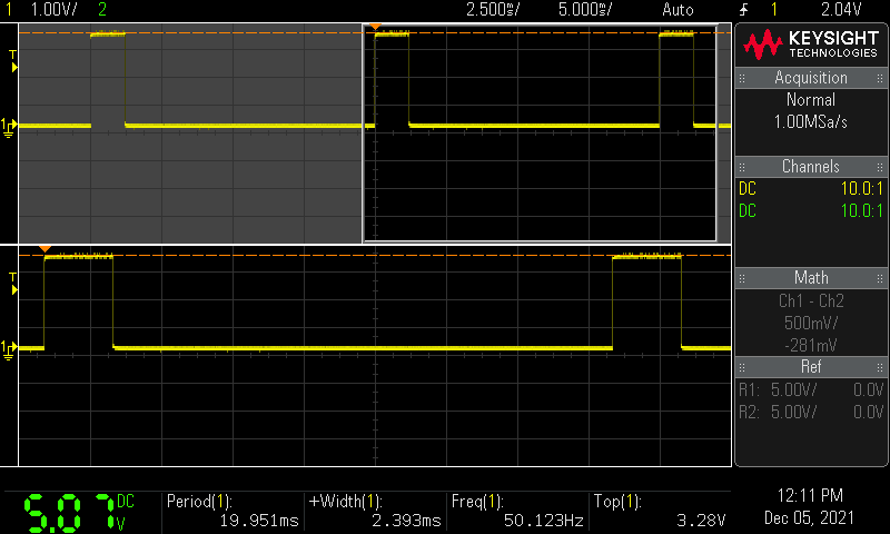
- サーボに供給している電圧: 5.07 V
- PWM信号周期: 19.946ms≈20ms
- Duty Cycle: 499μs≈0.5ms
- PWM信号電圧: 3.28V
周波数と周期の関係は f=T1 なので 19.946×10−31=50.135Hz
 angle0
サーボ角度 45 度
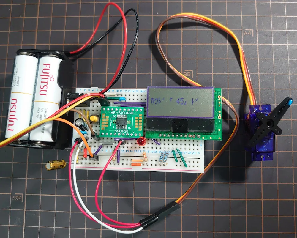 angle45
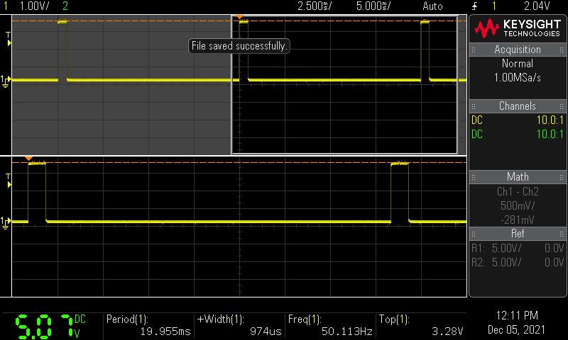
- Duty Cycle: 974μs≈0.97ms
サーボ角度 90 度
 angle90
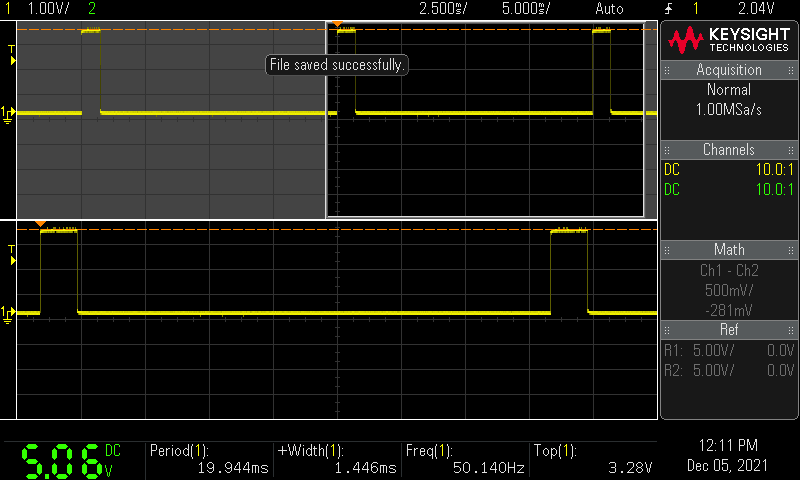
- Duty Cycle: 1.446ms≈1.45ms
サーボ角度 135 度
 angle135
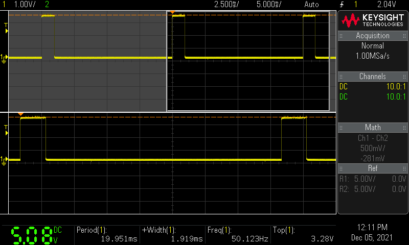
- Duty Cycle: 1.919ms≈1.92ms
サーボ角度 180 度
 angle180
- Duty Cycle: 2.393ms≈2.4ms
ここでもう一度マイクロサーボSG-90のデータシートを確認すると
SG-90_ds
データシートに書かれたとおりの信号を与えている。
Position “0” (1.45 ms pulse) is middle, “90” (~2.4 ms pulse) is all the way to the right,
“-90” (~ 0.5 ms pulse) is all the way left.
データシートには
- 1.45 ms pulse の時に「中心」
- 2.4 ms pulse の時に「右端」
- 0.5 ms pulse の時に「左端」
となっているが, 今回は時計回りいっぱいを角度0, 反時計回りいっぱいを角度180にした。
GitHubリポジトリ
https://github.com/ak1211/hello_stm32l0/tree/Servo
https://github.com/ak1211/hello_stm32l0/releases/tag/Servo